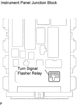
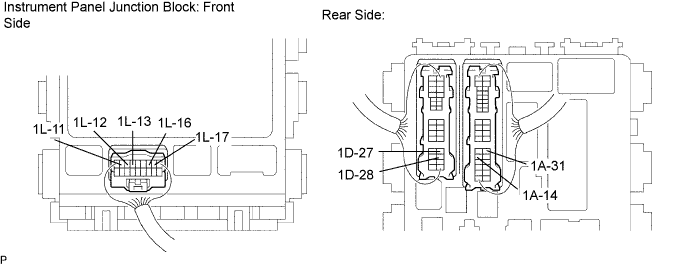
Tester Connection
| Condition
| Specified Condition
|
1A-14 - Body ground
| Hazard warning switch OFF
| Below 1 V
|
Hazard warning switch ON
| Alternating between Below 1 V to 9 V (60 to 120 times per minute)
|
1A-14 - Body ground
| Turn signal switch (left turn) OFF
| Below 1 V
|
Turn signal switch (left turn) ON
| Alternating between Below 1 V to 9 V (60 to 120 times per minute)
|
1A-31 - Body ground
| Hazard warning switch OFF
| Below 1 V
|
Hazard warning switch ON
| Alternating between Below 1 V to 9 V (60 to 120 times per minute)
|
1A-31 - Body ground
| Turn signal switch (right turn) OFF
| Below 1 V
|
Turn signal switch (right turn) ON
| Alternating between Below 1 V to 9 V (60 to 120 times per minute)
|
1D-27 - Body ground
| Hazard warning signal OFF
| Below 1 V
|
Hazard warning signal ON
| Alternating between Below 1 V to 9 V (60 to 120 times per minute)
|
1D-27 - Body ground
| Turn signal switch (left turn) OFF
| Below 1 V
|
Turn signal switch (left turn) ON
| Alternating between Below 1 V to 9 V (60 to 120 times per minute)
|
1D-28 - Body ground
| Hazard warning signal OFF
| Below 1 V
|
Hazard warning signal ON
| Alternating between Below 1 V to 9 V (60 to 120 times per minute)
|
1D-28 - Body ground
| Turn signal switch (right turn) OFF
| Below 1 V
|
Turn signal switch (right turn) ON
| Alternating between Below 1 V to 9 V (60 to 120 times per minute)
|
1L-11 - Body ground
| Turn signal switch (left turn) OFF
| Below 1 V
|
Turn signal switch (left turn) ON
| Above 9 V
|
1L-12 - Body ground
| Turn signal switch (right turn) OFF
| Below 1 V
|
Turn signal switch (right turn) ON
| Above 9 V
|
1L-13 - Body ground
| Hazard warning switch OFF
| Below 1 V
|
Hazard warning switch ON
| Alternating between Below 1 V to 9 V (60 to 120 times per minute)
|
1L-13 - Body ground
| Turn signal switch (left turn) OFF
| Below 1 V
|
Turn signal switch (left turn) ON
| Alternating between Below 1 V to 9 V (60 to 120 times per minute)
|
1L-16 - Body ground
| Hazard warning switch OFF
| Below 1 V
|
Hazard warning switch ON
| Alternating between Below 1 V to 9 V (60 to 120 times per minute)
|
1L-16 - Body ground
| Turn signal switch (right turn) OFF
| Below 1 V
|
Turn signal switch (right turn) ON
| Alternating between Below 1 V to 9 V (60 to 120 times per minute)
|
1L-17 - Body ground
| Hazard warning switch OFF
| Below 1 V
|
Hazard warning switch ON
| Above 9 V
|