Home › ENGINE › 1NZ-FXE EMISSION CONTROL › FUEL TANK PRESSURE SENSOR

FUEL TANK PRESSURE SENSOR > INSTALLATION

for Preparation Click here


1. INSTALL FUEL TANK PRESSURE SENSOR


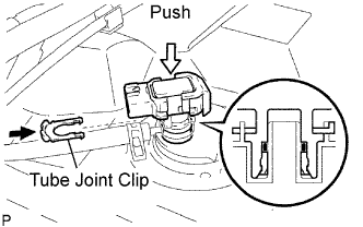
    A087518E01
  1. Push the fuel tank pressure sensor to the plug of the fuel tank retainer, then install the tube joint clip.

    NOTICE:
    1. Check that there are no scratches or foreign objects around the connected part of the fuel tank pressure sensor and fuel tank retainer before this work.
    2. Check that the fuel tank pressure sensor is securely inserted to the end.
    3. Check that the tube joint clip is on the collar of the fuel tank pressure sensor.
    4. After installing the tube joint clip, check that the fuel tank pressure sensor cannot be pulled out.
  1. Connect the fuel tank pressure sensor connector.


2. INSTALL FUEL TANK SUB-ASSEMBLY
  1. Set the fuel tank to a transmission jack.

  1. Operate the transmission jack, and then install the fuel tank to the vehicle.

  1. Operate the transmission jack, and then connect the fuel tank inlet pipe.


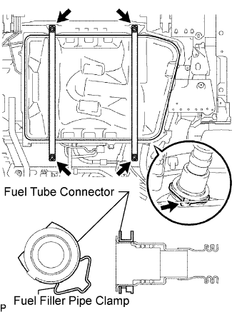
    A087489E02
  1. Install the No. 1 fuel tank band RH and LH with the 4 bolts.

    Torque:
    39 N*m{ 400 kgf*cm , 29 ft.*lbf }

  1. Install the fuel tube connector and fuel filler pipe clamp to the fuel tank inlet pipe.


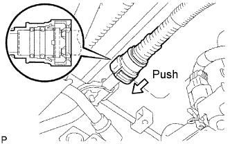
    A087510E01
  1. Connect the No. 1 canister tube.

    1. Align the No. 1 canister tube connector with the pipe, and then push in the No. 1 canister tube connector until the retainer makes a "click" sound to connect the No. 1 canister tube to the fuel tank to filler pipe.

      NOTICE:
      1. Check that there are no scratches or foreign objects around the connected part of the No. 1 canister tube connector and pipe before this procedure.
      2. After connecting the No. 1 canister tube, check that the No. 1 canister tube is securely connected by pulling the No. 1 canister tube connector.


    A087511E01
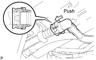
  1. Connect the fuel suction tube.

    1. Align the suction tube connector with the pipe, and then push in the suction tube connector until the retainer makes a "click" sound to connect the fuel suction tube to the fuel tank to filler pipe.

      NOTICE:
      1. Check that there are no scratches or foreign objects around the connected part of the suction tube connector and pipe before this procedure.
      2. After connecting the fuel suction tube, check that the fuel suction tube is securely connected by pulling the suction tube connector.


    A087512E01
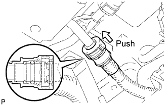
  1. Connect the fuel tank vent hose.

    1. Align the fuel tank vent hose connector with the pipe, and then push in the fuel tank vent hose connector until the retainer makes a "click" sound to connect the fuel tank vent hose to the canister filter.

      NOTICE:
      1. Check that there are no scratches or foreign objects around the connected part of the fuel tank vent hose connector and pipe before this procedure.
      2. After connecting the fuel tank vent hose, check that the fuel tank vent hose is securely connected by pulling the vent hose connector.


    A091721E02
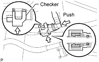
  1. Connect the No. 2 fuel tank main tube.

    1. Align the fuel tube connector with the pipe, and then push in the fuel tube connector until the retainer makes a "click" sound to connect the No. 2 fuel tank main tube to the pipe.

      NOTICE:
      1. Check that there are no scratches or foreign objects around the connected part of the fuel tube connector and pipe before this procedure.
      2. After connecting the No. 2 fuel tank main tube, check that the No. 2 fuel tank main tube is securely connected by pulling the quick connector.

  1. Install the checker to the pipe.


    A087603E02
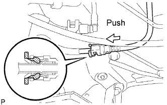
  1. Connect the fuel tank to canister tube.

    1. Align the fuel tank to canister tube connector with the pipe, and then push in the fuel tank to canister tube connector until the retainer makes a "click" sound to connect the fuel tank to canister tube to the pipe.

      NOTICE:
      1. Check that there are no scratches or foreign objects around the connected part of the fuel tank to canister tube connector and pipe before this procedure.
      2. After connecting the fuel tank to canister tube, check that the fuel tank to canister tube is securely connected by pulling the quick connector.


3. INSTALL FRONT EXHAUST PIPE


    A111834
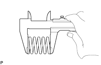
  1. Using a vernier caliper, measure the free length of the compression spring.

    Minimum length:
    40.5 mm (1.594 in.)

    If the length is less than the minimum, replace the compression spring.


    A076194E04
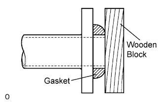
  1. Using a plastic-faced hammer and wooden block, tap in a new gasket until its surface is flush with the exhaust manifold.

    NOTICE:
    1. Tap in the gasket in the correct direction.
    2. Do not reuse the removed gasket.
    3. Do not push in the gasket while installing the exhaust pipe.

  1. Connect the 2 exhaust pipe supports, and install the exhaust pipe.

  1. Install the 2 compression springs and 2 bolts.

    Torque:
    43 N*m{ 438 kgf*cm , 32 ft.*lbf }


    A087437
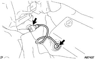
  1. Install the grommet of the heated oxygen sensor to the vehicle.

  1. Connect the heated oxygen sensor connector.

  1. Install the front floor carpet with the clip.


4. CONNECT CABLE TO NEGATIVE BATTERY TERMINAL

NOTICE:
  1. When the warning light is illuminated or the battery has been disconnected and reconnected, turning the power switch may not start the system on the first try. If so, turn the power switch again.
  2. With the power switch's power mode changed to ON (IG), disconnect the battery. If the key is not in the key slot during reconnection, DTC B2799 may be output.


    A088356E01
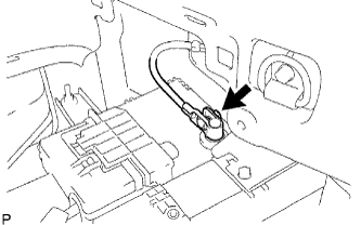
  1. Connect the battery negative cable, and then tighten the nut.

    Torque:
    6.0 N*m{ 61 kgf*cm , 53 in.*lbf }


5. INSPECT FOR FUEL LEAK
  1. Check that there are no leaks in the fuel system while fuel pressure is applied.


6. INSPECT FOR EXHAUST GAS LEAK
If gas is leaking, tighten the problem areas to stop the leak. Replace damaged parts as necessary.


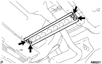
7. INSTALL FRONT FLOOR PANEL BRACE


    A086201
  1. Install the floor panel brace with the 2 bolts.

    Torque:
    30 N*m{ 302 kgf*cm , 22 ft.*lbf }


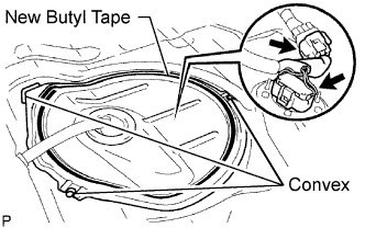
8. INSTALL REAR FLOOR SERVICE HOLE COVER


A087515E02
  1. Attach new butyl tape to the rear floor service hole cover.

  1. Connect the wire to wire connector.

  1. Connect the fuel pump connector.

  1. Install the rear floor service hole cover while adjusting it to the 3 convex parts of the floor panel.

    NOTICE:
    Be careful that the rear floor service hole cover does not overlap the convex parts of the floor panel when installing.


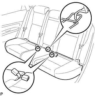
9. INSTALL REAR SEAT CUSHION ASSEMBLY

NOTICE:
When installing the seat cushion, make sure the seat belt buckle is not under the seat cushion.


    B132601E01
  1. Attach the seat cushion's rear hook to the center hinge.

  1. Insert the inner belts through the slits on the seat cushion.


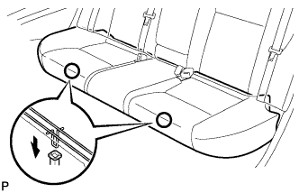
    B132602
  1. Attach the seat cushion's 2 front hooks to the vehicle body.

  1. Confirm that the seat cushion is firmly installed.


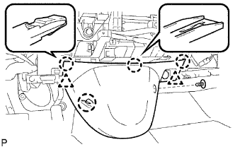
10. INSTALL LOWER CENTER INSTRUMENT PANEL FINNISH PANEL


B074061E03
  1. Attach the 4 claws and 2 clips to install the instrument panel finish panel.

  1. Install the clip.


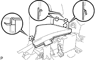
11. INSTALL REAR NO. 3 FLOOR BOARD


    A088355E02
  1. Install the floor board, and then attach the 4 claws.


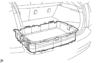
12. INSTALL REAR DECK FLOOR BOX


    A088354E01
  1. Install the rear deck floor box to the vehicle.


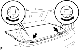
13. INSTALL REAR NO. 2 FLOOR BOARD


    A088353E01
  1. Install the floor board, and then lock the 2 cover knobs.


14. PERFORM INITIALIZATION
  1. Perform initialization (Click here).

    NOTICE:
    Certain systems need to be initialized after disconnecting and reconnecting the cable from the negative (-) battery terminal.