Home › HYBRID SYSTEM › P112 HYBRID VEHICLE CONTROL › HYBRID CONTROL SYSTEM

DTC    P0AE7-224    Hybrid Battery Precharge Contactor Control Circuit High

DTC    P0AE6-225    Hybrid Battery Precharge Contactor Control Circuit Low

for Preparation Click here


DESCRIPTION

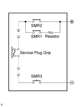
A093714E01
The SMRs (System Main Relays) connect and disconnect the high-voltage power supply circuit in accordance with requests from the HV control ECU. To ensure a reliable operation, they consists of a total of 3 relays (1 for the negative side and 2 for the positive side).
To connect, SMR1 and SMR3 turn ON initially. Then, SMR2 turns ON and SMR1 turns OFF. This process protects the circuit from the high-voltage surge current by allowing the limit current to flow via the resistor. To disconnect, SMR2 and SMR3 turn OFF in that order. The HV control ECU checks that the relays have turned OFF properly.
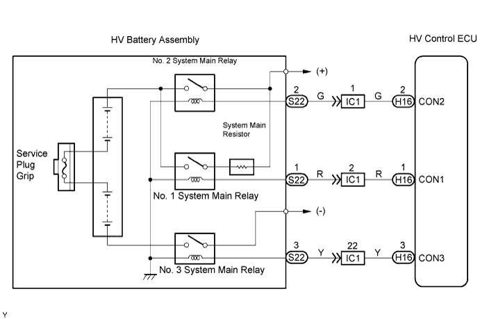
The HV control ECU monitors the proper operation of the SMRs (CON1, CON2 and CON3) to check for a malfunction.

DTC No.
INF Code
DTC Detection Condition
Trouble Area
P0AE7
224
Open or +B short in No. 1 system main relay circuit
  1. Wire harness or connector
  2. No. 1 system main relay
  3. HV control ECU
P0AE6
225
GND short in No. 1 system main relay circuit
  1. Wire harness or connector
  2. No. 1 system main relay
  3. HV control ECU

WIRING DIAGRAM


A092107E04


INSPECTION PROCEDURE

CAUTION:
  1. Before inspecting the high-voltage system, take safety precautions to prevent electrical shocks, such as wearing insulated gloves and removing the service plug grip. After removing the service plug grip, put it in your pocket to prevent other technicians from reconnecting it while you are servicing the high-voltage system.
  2. After disconnecting the service plug grip, wait for at least 5 minutes before touching any of the high-voltage connectors or terminals.

HINT:
At least 5 minutes are required to discharge the high-voltage condenser inside the inverter.

1.INSPECT NO. 1 SYSTEM MAIN RELAY
  1. Inspect the No. 1 system main relay .


NG
REPLACE NO. 1 SYSTEM MAIN RELAY
OK


2.CHECK HARNESS AND CONNECTOR (HYBRID VEHICLE CONTROL ECU - NO. 1 SYSTEM MAIN RELAY)

CAUTION:
Wear insulated gloves before performing the following operation.

  1. Turn the power switch OFF.

  1. Remove the service plug grip .

    NOTICE:
    Turning the power switch ON (READY) with the service plug grip removed could cause malfunction. Therefore, never turn the power switch ON (READY) in this state.


    A065745E42
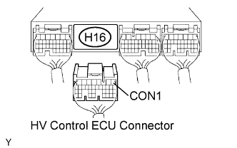
  1. Disconnect the H16 HV control ECU connector.
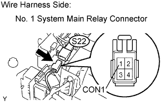


    A093715E04
  1. Disconnect the S22 No. 1 system main relay connector.

  1. Turn the power switch ON (IG).

    HINT:
    DTCs for the interlock switch system are output when turning the power switch ON (IG) with the service plug grip removed.

  1. Measure the voltage between the terminal of the HV control ECU connector and body ground.

    Standard voltage:
    Tester Connection
    Specified Condition
    CON1 (H16-1) - Body ground
    Below 1 V

  1. Turn the power switch OFF.

  1. Measure the resistance between the wire harness side connectors.

    Standard resistance (Check for open):
    Tester Connection
    Specified Condition
    CON1 (H16-1) - CON1 (S22-1)
    Below 1 Ω
    Standard resistance (Check for short):
    Tester Connection
    Specified Condition
    CON1 (H16-1) or CON1 (S22-1) - Body ground
    10 kΩ or higher

  1. Reconnect the No. 1 system main relay connector.

  1. Reconnect the HV control ECU connector.

  1. Reinstall the service plug grip .


NG
REPAIR OR REPLACE HARNESS OR CONNECTOR
OK

REPLACE HYBRID VEHICLE CONTROL ECU