BODY WELD POINT QUARTER PANEL CUT AND JOIN REPLACEMENT SECTIONS (SMALL AREAS)
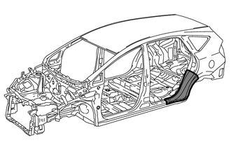
Quarter Panel Replacement Using Adhesive
Cut the wheel arch portion.
Heat the quarter panel adhesive area and remove the quarter panel.
- HINT:
-
Using an industrial heater gun or gas burner, heat the quarter panel to 110 to 140°C. Make sure the quarter panel does not warp.
Clean off any adhesive that remains on the vehicle.
- HINT:
- ·
Using an industrial heater gun or gas burner, heat the adhesive to 110 to 140°C.
·Using a scraper, scrape away the adhesive.
·If adhesive remains, the strength of any subsequently applied adhesive will be weak.
Using a disc grinder or belt sander, scuff and sand any adhesive that remains on the vehicle.
- HINT:
-
Scuff at a width of approximately 10 mm (0.39 in.) over the previous adhesive coating.
Apply adhesive to the exposed metal areas on the vehicle. Using a spatula, spread the adhesive evenly.
Apply adhesive to the vehicle again.
Using #60-120 grit sandpaper, scuff the adhesive application area on the new quarter panel.
Apply adhesive to the new quarter panel. Using a spatula, spread the adhesive evenly.
Using a vise grip or the palms of your hands, press the quarter panel so that the thickness of the adhesive is even.
Complete installation the new quarter panel.
Dry the adhesive areas of the new quarter panel.
- HINT:
- ·
With dryer or equivalent (60°C): 60 minutes (complete hardening: 90 minutes)
·Ambient temperature (25°C): 12 hours (complete hardening: 24 hours)
REMOVAL
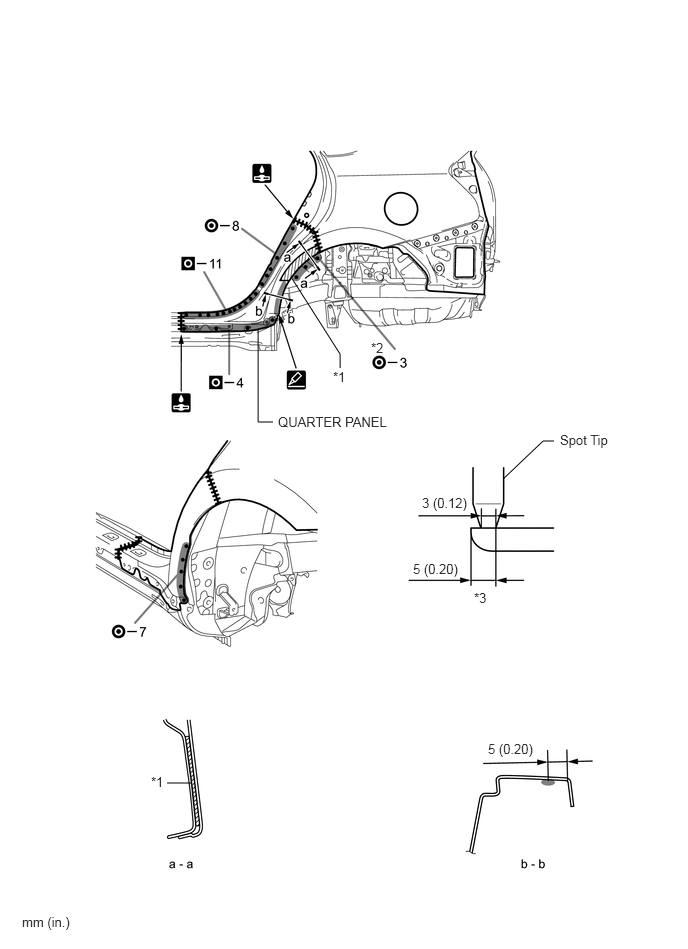
| Symbol meaning | |
|---|---|

|
Remove Weld Points |

|
Cut and Join Location |

|
Cut Location for Supply Parts |
*1 in illustration above indicates where the adhesive is located.
Roughly cut open the panel so that the adhesive can be reached. Cut through the adhesive with a cut chisel to remove the panel.
- HINT:
-
In cases where the adhesive cannot be removed with a cut chisel, heat the adhesive with an industrial heater gun or gas burner taking care not to cause panel deformation by overheating.
INSTALLATION
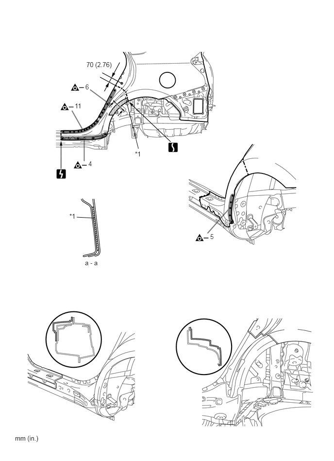
| Symbol meaning | |
|---|---|

|
Spot Weld |

|
Plug Weld |

|
Butt Weld |

|
Body Sealer |
Inspect the fitting of the related parts around the new parts before welding. This affects the appearance of the finish.
Temporarily install the new parts and measure each part of the new parts in accordance with the body dimension diagram. (See the body dimensions)
Before installing a new part, apply body sealer.
- HINT:
- ·
Apply body sealer evenly about 5 mm (0.20 in.) from the flange, avoiding any oozing.
·Apply body sealer evenly, about 3 to 4 mm (0.12 to 0.16 in.) in diameter.
Apply adhesive (3MTM AutomixTM Panel Bonding Adhesive #8115) to the area indicated by *1 in the illustration.
- HINT:
-
Apply enough adhesive for the panels to stick to each other.
Perform spot-welding on the flange indicated by *2 in the illustration. Modify/cut the spot tip as shown in the illustration*3 so that it can fit in to the narrow flange.
After welding, apply body sealer to the corresponding parts. (See the painting / coating)
After applying the top coat, apply anti-rust agent to the internal panel portion of the closed section structural weld points.