Home › Brake › BRAKE CONTROL / DYNAMIC CONTROL SYSTEMS › BRAKE CONTROL SYSTEM › 2014.11–2016.05
NM2070E _54 Brake _061874 BRAKE CONTROL / DYNAMIC CONTROL SYSTEMS _0301413 BRAKE CONTROL SYSTEM UN GENERAL/CONTROL/DETAILS F

BRAKE CONTROL / DYNAMIC CONTROL SYSTEMS  BRAKE CONTROL SYSTEM  GENERAL/CONTROL/DETAILS  GENERAL  


OUTLINE


a.

The brake actuator and the skid control ECU are integrated and a hydraulic brake booster is provided, thus optimizing the hydraulic circuit and offering a weight reduction.


b.

Brake control functions (ABS with EBD, Brake Assist, TRC, Hill-start Assist Control and VSC+) are provided.


c.

A VSC+ that performs cooperative control with the EPS is used.


d.

An electronically controlled brake system is used to control the hydraulic pressure at the 4 wheels.


e.

A regenerative brake cooperative control is used.


f.

An emergency brake signal is used. This signal is provided to indicate that strong braking is being performed by the driver.


MAJOR DIFFERENCE


a.

The new models have been modified from the previous models as shown below:

i.

Hill-start Assist Control has been changed.


MAIN FEATURES


a.

Electronically Controlled Brake System

i.

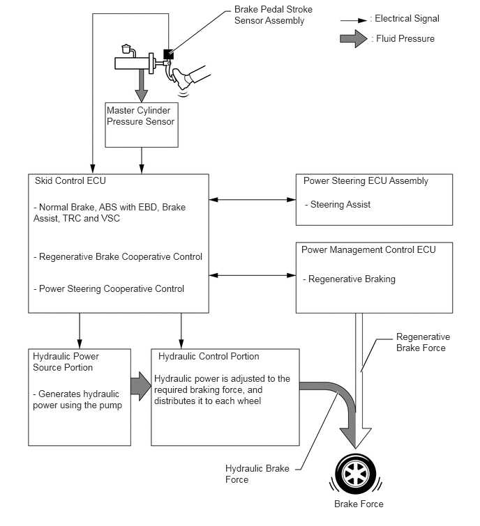
In this system, the conventional brake booster portion has been discontinued. Instead, it consists of hydraulic brake booster, brake actuator and brake booster pump assembly.


ii.

During normal braking, fluid pressure generated by the hydraulic brake booster does not directly actuate the wheel cylinders, but serves as a hydraulic pressure signal. Instead, the actual control pressure is obtained by regulating the fluid pressure of the brake booster pump assembly, which actuates the wheel cylinders.
U191457E02
5.052,5.854 4.49,7.021 4.49,7.021 4.406,7.021 true 2.531,0.802 3.365,0.167 3.365,0.167 3.448,0.167 true 5.865,5.073 5.615,5.073 false 4.531,2.615 6.552,2.844 2.021,0.229 10 false Power Steering ECU Assembly 4.5,3.646 6.594,3.885 2.094,0.24 10 false Power Management Control ECU 5.917,4.948 6.75,5.323 0.833,0.375 10 false Regenerative Brake Force 3.365,6.917 4.385,7.406 1.021,0.49 10 false Hydraulic Brake Force 4.99,7.448 5.833,7.708 0.844,0.26 10 false Brake Force 2.365,5.24 3.938,5.438 1.573,0.198 10 false Hydraulic Control Portion 0.49,5.24 1.542,5.615 1.052,0.375 10 false Hydraulic Power Source Portion 5.521,0.188 6.708,0.396 1.188,0.208 10 false : Electrical Signal 5.542,0.49 6.635,0.677 1.094,0.188 10 false : Fluid Pressure 0.521,2.615 1.729,2.823 1.208,0.208 10 false Skid Control ECU 1.594,1.563 2.625,2.052 1.031,0.49 10 false Master Cylinder Pressure Sensor 3.5,0.052 4.75,0.469 1.25,0.417 10 false Brake Pedal Stroke Sensor Assembly 0.5,3.01 2.885,3.365 2.385,0.354 10 false - Normal Brake, ABS with EBD, Brake Assist, TRC and VSC 0.5,3.75 3.052,4.01 2.552,0.26 10 false - Regenerative Brake Cooperative Control 0.5,4.229 2.792,4.448 2.292,0.219 10 false - Power Steering Cooperative Control 0.49,5.802 1.875,6.219 1.385,0.417 10 false - Generates hydraulic power using the pump 2.302,5.573 4.396,6.125 2.094,0.552 10 false Hydraulic power is adjusted to the required braking force, and distributes it to each wheel 4.521,4.083 6.073,4.313 1.552,0.229 10 false - Regenerative Braking 4.552,2.969 5.688,3.188 1.135,0.219 10 false - Steering Assist


iii.

When the skid control ECU detects a fault in the system, brake force can be ensured by applying the brake using fluid pressure boosted by the hydraulic brake booster.


b.

Regenerative Brake Cooperative Control

i.

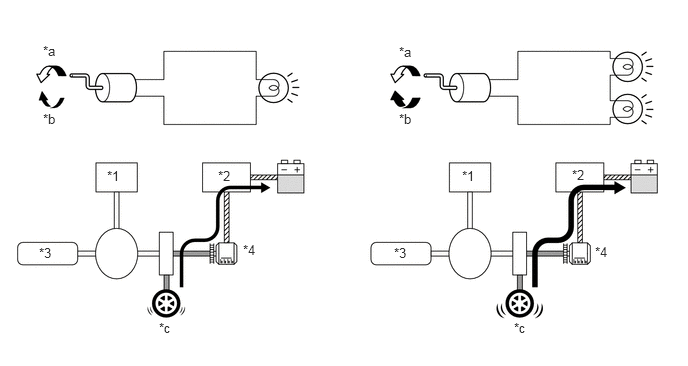
Regenerative braking consists of a resistance force that is generated at the rotational axle in the reverse direction of the rotation of the generator (MG2) that is generating electricity. The greater the generated amperage (battery charging amperage), the greater the resistance force will be.
X101531E07
4.156,0.458 4.354,0.656 0.198,0.198 10 false *a 4.156,1.156 4.344,1.396 0.188,0.24 10 false *b 4.104,2.552 4.406,2.729 0.302,0.177 10 false *3 2.531,2.521 2.833,2.698 0.302,0.177 10 false *4 0.406,2.552 0.708,2.729 0.302,0.177 10 false *3 4.813,1.75 5.115,1.927 0.302,0.177 10 false *1 5.958,1.74 6.26,1.917 0.302,0.177 10 false *2 6.198,2.542 6.5,2.719 0.302,0.177 10 false *4 5.354,3.333 5.656,3.51 0.302,0.177 10 false *c 2.271,1.75 2.573,1.927 0.302,0.177 10 false *2 1.115,1.75 1.417,1.927 0.302,0.177 10 false *1 0.448,0.448 0.677,0.656 0.229,0.208 10 false *a 0.448,1.156 0.677,1.365 0.229,0.208 10 false *b 1.656,3.333 1.885,3.542 0.229,0.208 10 false *c

Text in Illustration
*1 MG1 *2 Inverter
*3 Engine *4 MG2
*a Rotating direction to electricity generation *b Resistance
*c Brake Force - -


ii.

The drive wheels and MG2 are joined mechanically. When the drive wheels rotate MG2 and cause it to operate as a generator, a regenerative brake force of MG2 is transmitted to the drive wheels. Based on the signals from the skid control ECU, this force is controlled by the hybrid system, which controls the generation of electricity.


iii.

The regenerative brake cooperative control does not rely solely on the braking force of the hydraulic brake system to supply the brake force required by the driver. Instead, by effecting cooperative control with the hybrid system, this control provides a joint braking force provided by the regenerative braking and the hydraulic braking. As a result, this control minimizes the loss of the kinetic energy associated with the normal hydraulic braking, and recovers this energy by converting it into electrical energy.


iv.

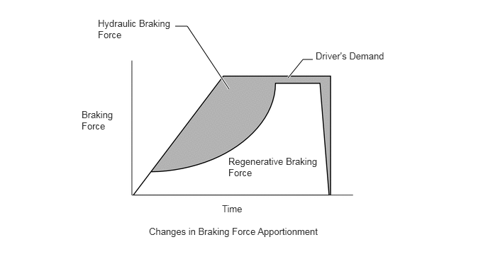
The apportioning of the brake force between the hydraulic braking and the regenerative braking varies by the vehicle speed and braking time.


v.

The apportioning of the brake force between the hydraulic braking and the regenerative braking is accomplished by controlling the hydraulic braking so that the total brake force of the hydraulic braking and the regenerative braking matches the brake force required by the driver.


vi.

If the regenerative braking becomes inoperative due to a malfunction in the hybrid system, the brake system effects control so that the entire brake force required by the driver is supplied with the hydraulic brake system.
X101475E28
2.573,0.385 2.75,0.385 2.75,0.385 3.365,1.313 true 4.594,0.875 4.448,0.875 4.448,0.875 4.229,1.146 true 1.198,1.604 1.729,1.99 0.531,0.385 10 false Braking Force 1.438,0.26 2.573,0.615 1.135,0.354 10 false Hydraulic Braking Force 4.635,0.74 5.719,1.01 1.083,0.271 10 false Driver's Demand 3.354,2.292 4.688,2.656 1.333,0.365 10 false Regenerative Braking Force 3.26,2.99 3.656,3.219 0.396,0.229 10 false Time 2.188,3.323 4.823,3.677 2.635,0.354 10 false Changes in Braking Force Apportionment


c.

VSC+

i.

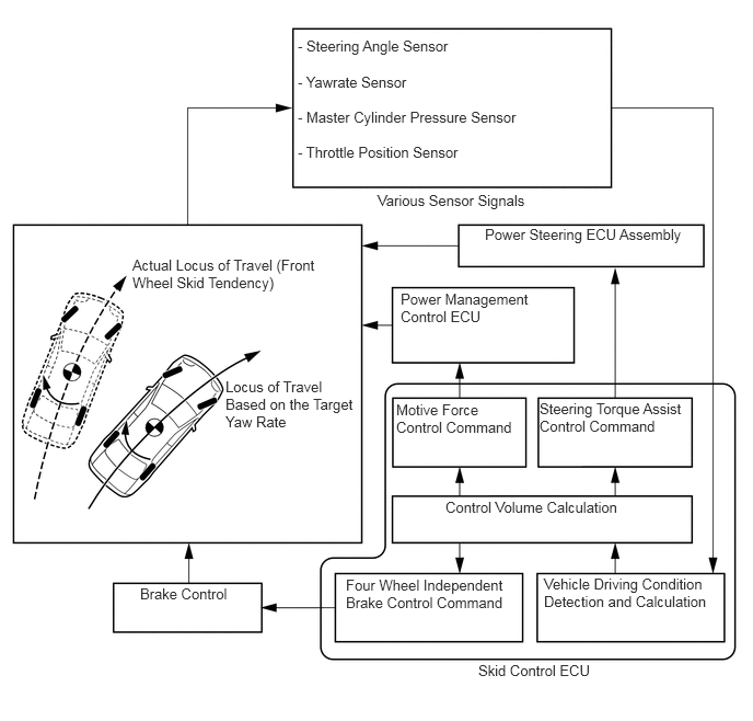
In the past, the brake control functions (ABS, TRC, VSC) and the Electronic Power Steering (EPS) were controlled individually. In contrast, the new model uses a VSC+, which uses a cooperative control with EPS. This system effects the controls integrated with the brake control functions and the EPS in accordance with driving conditions. Thus, it realizes dynamic performance of the vehicle's ability to "run, turn and stop" and ensures excellent driving stability and drivability.
X104970E22
2.833,0.354 4.479,0.563 1.646,0.208 10 false - Steering Angle Sensor 2.833,0.698 4.021,0.906 1.188,0.208 10 false - Yawrate Sensor 2.833,1.031 5.042,1.24 2.208,0.208 10 false - Master Cylinder Pressure Sensor 2.833,1.365 4.448,1.573 1.615,0.208 10 false - Throttle Position Sensor 3.594,1.823 5.135,2.042 1.542,0.219 10 false Various Sensor Signals 4.615,2.146 6.583,2.354 1.969,0.208 10 false Power Steering ECU Assembly 1.26,2.438 3.052,2.854 1.792,0.417 10 false Actual Locus of Travel (Front Wheel Skid Tendency) 2.146,3.594 3.385,4.323 1.24,0.729 10 false Locus of Travel Based on the Target Yaw Rate 1.333,5.563 2.26,5.76 0.927,0.198 10 false Brake Control 3.813,2.76 5.083,3.135 1.271,0.375 10 false Power Management Control ECU 3.771,3.813 4.969,4.208 1.198,0.396 10 false Motive Force Control Command 5.135,3.802 6.563,4.396 1.427,0.594 10 false Steering Torque Assist Control Command 4.24,4.74 5.958,4.958 1.719,0.219 10 false Control Volume Calculation 3.292,5.479 4.844,5.865 1.552,0.385 10 false Four Wheel Independent Brake Control Command 5.177,5.469 6.771,5.854 1.594,0.385 10 false Vehicle Driving Condition Detection and Calculation 4.552,6.292 5.76,6.479 1.208,0.188 10 false Skid Control ECU


PRECAUTION


a.

When the brake control system is activated, the brake pedal may shudder, which is a normal occurrence of the system in operation and should not be considered a malfunction.