HYBRID / BATTERY CONTROL HYBRID CONTROL SYSTEM P0A4B-253 Generator Position Sensor Circuit P0A4C-513 Generator Position Sensor Circuit Range / Performance P0A4D-255 Generator Position Sensor Circuit Low
DESCRIPTION
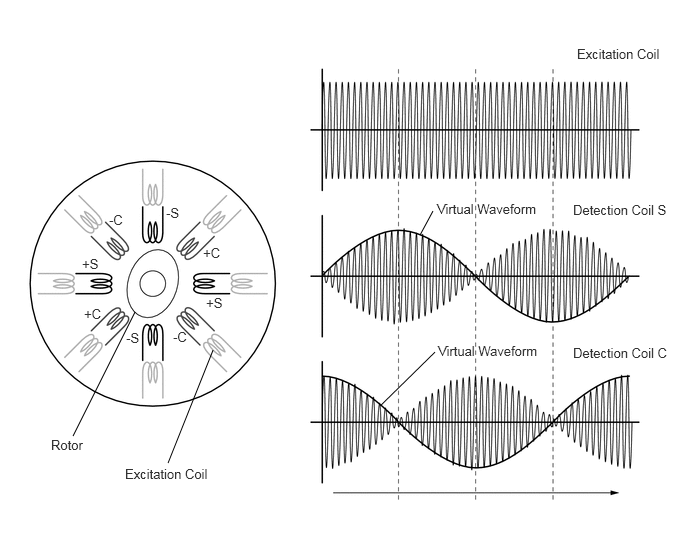
A resolver is a sensor that is used to detect the position of the magnetic poles the rotor of a motor generator. Knowing the position of the poles is indispensable for ensuring precise control of MG2 and MG1.
Each resolver contains a stator that has an excitation coil and 2 detection coils (S, C). The gap between the stator and rotor changes as the rotor turns because the rotor is oval shaped. An alternating current with a predetermined frequency flows through the excitation coil, and detection coils S and C output alternating currents in accordance with the sensor rotor position.
The inverter with converter assembly (MG ECU) detects the absolute position of the rotor according to the phases of detection coils S and C and the heights of their waveforms. Furthermore, the CPU calculates the amount of change in the position within a predetermined length of time, in order to use the resolver as a speed sensor.
The MG ECU monitors signals output from the motor resolver and detects malfunctions.
| DTC No. | INF Code | DTC Detection Condition | Trouble Area |
|---|---|---|---|
| P0A4B | 253 | Interphase short in the generator resolver circuit | ·
Inverter with converter assembly ·
Hybrid vehicle generator assembly ·
Hybrid vehicle motor assembly ·
Wire harness or connector |
| P0A4C | 513 | Generator resolver output is out of the normal range | |
| P0A4D | 255 | Open or short in the generator resolver circuit |
WIRING DIAGRAM
Refer to the wiring diagram for DTC P1CAC-200 (See page Engine / Hybrid System>HYBRID / BATTERY CONTROL>HYBRID CONTROL SYSTEM>P1CAC-200).
CAUTION / NOTICE / HINT
- CAUTION:
- ·
Before inspecting the high-voltage system or disconnecting the low voltage connector of the inverter with converter assembly, take safety precautions such as wearing insulated gloves and removing the service plug grip to prevent electrical shocks. After removing the service plug grip, put it in your pocket to prevent other technicians from accidentally reconnecting it while you are working on the high-voltage system.
·After removing the service plug grip, wait for at least 10 minutes before touching any of the high-voltage connectors or terminals. After waiting for 10 minutes, check the voltage at the terminals in the inspection point in the inverter with converter assembly. The voltage should be 0 V before beginning work (See page Engine / Hybrid System>HYBRID / BATTERY CONTROL>HYBRID CONTROL SYSTEM>PRECAUTION).
- HINT:
-
Waiting for at least 10 minutes is required to discharge the high-voltage capacitor inside the inverter with converter assembly.
- NOTICE:
-
After turning the power switch off, waiting time may be required before disconnecting the cable from the negative (-) auxiliary battery terminal. Therefore, make sure to read the disconnecting the cable from the negative (-) auxiliary battery terminal notices before proceeding with work (See page General>INTRODUCTION>REPAIR INSTRUCTION>PRECAUTION).
- HINT:
- ·
If the problem symptom cannot be reproduced, performing a road test on a road on which the vehicle tends to vibrate will make it easier to reproduce the symptom.
·After the repair, clear the DTCs and perform the following procedure to check that DTCs are not output.
(a)Turn the power switch on (IG) and wait for 5 seconds or more.
(b)Turn the power switch on (READY) with park (P) selected and wait for 5 seconds or more.
(c)Depress the accelerator pedal of the vehicle with the engine stopped and park (P) selected to start the engine.
(d)Keep the engine running for 5 seconds or more.
(e)Drive the vehicle forward with drive (D) selected for 5 m or more.
(f)Drive the vehicle backward with reverse (R) selected for 5 m or more.
PROCEDURE
OK
NG
OK
NG
OK
NG
OK
NG
OK
NG
OK
NG
OK
NG
OK
NG
OK
NG
OK
NG
OK
NG