HYBRID / BATTERY CONTROL HYBRID CONTROL SYSTEM P0AC0-817 Hybrid Battery Pack Current Sensor Circuit Range / Performance
DESCRIPTION
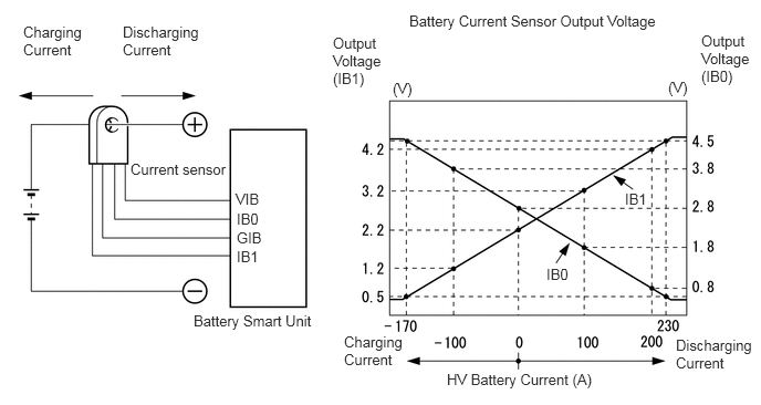
A battery current sensor, which is mounted on the positive cable side of each hybrid battery junction block assembly, detects the current flowing to or from the battery pack. The battery current sensor sends a voltage, which varies between 0 and 5 V in proportion to the amperage, to the IB0 terminal of the battery smart unit. Similarly, it sends a voltage, which varies between 0 and 5 V in inverse proportion to the amperage, into the IB1 terminal of the battery smart unit. When the voltage of the IB0 terminal is below 2.8 V and the voltage of the IB1 terminal is above 2.2 V, this indicates that the HV battery is being charged. Meanwhile, when the voltage of the IB0 terminal is above 2.8 V and the voltage of the IB1 terminal is below 2.2 V, this indicates that the HV battery is being discharged. The battery smart unit sends the signals from its IB0 and IB1 terminals to the hybrid vehicle control ECU (HV battery CPU). The hybrid vehicle control ECU (HV battery related portion) determines the charging and discharging amperage of the HV battery based on the received signals and calculates the SOC of the HV battery using the cumulative amperage value.
| DTC No. | INF Code | DTC Detection Condition | Trouble Area |
|---|---|---|---|
| P0AC0 | 817 | HV battery current sensor performance problem | ·
Hybrid battery junction block assembly ·
Battery smart unit |
CAUTION / NOTICE / HINT
- HINT:
-
After the repair, clear the DTCs and perform the following procedure to check that DTCs are not output.
- 1.
Drive the vehicle for approximately 10 minutes according to the freeze frame data items "Vehicle Spd", "Accelerator Degree", "Power Resource IB", "M(MG2) Trq Exec Val" and "G(MG1) Trq Exec Val".
PROCEDURE
Connect the GTS to the DLC3.
Turn the power switch on (IG).
Enter the following menus: Powertrain / Hybrid Control / Trouble Codes.
Check if DTCs are output.
- Result:
Result Proceed to P0AFC-123 is not output. A P0AFC-123 is output. B
Turn the power switch off.
A
B
Connect the GTS to the DLC3.
Turn the power switch on (IG).
Enter the following menus: Powertrain / Hybrid Control / Trouble Codes.
Check if DTCs are output.
- Result:
Result Proceed to P301A-123 is not output. A P301A-123 is output. B
Turn the power switch off.
A
B
NEXT
Connect the GTS to the DLC3.
Turn the power switch on (IG).
Enter the following menus: Powertrain / Hybrid Control / Trouble Codes.
Read and record the DTCs and freeze frame data.
Clear DTCs and freeze frame data.
Turn the power switch off.
NEXT
Connect the GTS to the DLC3.
Turn the power switch on (IG).
Enter the following menus: Powertrain / Hybrid Control / ECU Data List / State of Charge (All Bat).
Check that "State of Charge (All Bat)" shows 60% or less.
- HINT:
-
If "State of Charge (All Bat)" is 60% or more, reduce it to below 60% by leaving the hybrid system on with neutral (N) selected.
Apply the parking brake and secure the wheels using chocks.
Turn the power switch on (READY).
Move the shift lever to D while depressing the brake pedal with your left foot and repeat the following steps for 1 minute or more.
- HINT:
-
Depress and release the accelerator pedal in 5-second intervals (2.5 seconds each) continuously.
While depressing the brake pedal with your left foot, depress the accelerator pedal with your right foot.
Release the accelerator pedal.
Turn the power switch off.
NEXT
Connect the GTS to the DLC3.
Turn the power switch on (IG).
Enter the following menus: Powertrain / Hybrid Control / Trouble Codes.
Check if DTCs are output.
- Result:
Result Proceed to P0AC0-817 is not output. A P0AC0-817 is output again. B
Turn the power switch off.
A
B