Home › Engine / Hybrid System › HYBRID / BATTERY CONTROL › INVERTER CURRENT SENSOR
RM2070E _51 Engine / Hybrid System _061906 HYBRID / BATTERY CONTROL _0301590 INVERTER CURRENT SENSOR A

HYBRID / BATTERY CONTROL  INVERTER CURRENT SENSOR  DISASSEMBLY  


CAUTION / NOTICE / HINT

HINT:

For the disassembly procedure of the inverter with converter assembly, refer to the disassembly procedure of the MG control computer with bracket sub-assembly (See page Engine / Hybrid System>HYBRID / BATTERY CONTROL>MOTOR GENERATOR CONTROL COMPUTER>DISASSEMBLY).


PROCEDURE

Hide 1.REMOVE INVERTER CURRENT SENSOR SUB-ASSEMBLY

HINT:

The number of clamps used to engage the wire harnesses of the inverter current sensor sub-assembly varies depending on the part number of the inverter with converter assembly. Confirm the part number before performing work.
A330574E02
0.095,0 0.478,0.267 0.383,0.267 10 *A 3.612,0 4.082,0.332 0.471,0.332 10 *B

Text in Illustration
*A For inverter with converter assembly with part number G9200-47160, G9200-47161 or G9200-47162 *B For inverter with converter assembly with part number other than G9200-47160, G9200-47161 or G9200-47162

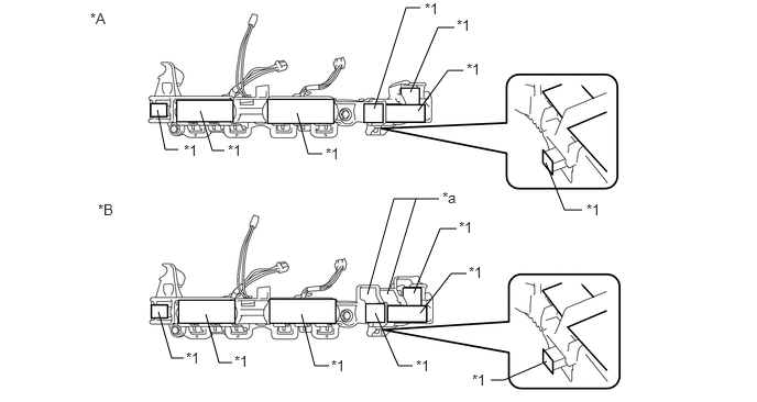
a.

Apply protective tape to the inverter terminal with sensor sub-assembly as shown in the illustration.

NOTICE:

Use non-residue type tape.


A330163E04
3.885,0.875 4.146,0.26 4.146,0.26 4.302,0.26 false 3.958,1.052 4.24,0.667 4.24,0.667 4.385,0.667 false 3.542,1.031 3.844,0.073 3.844,0.073 3.979,0.073 false 3.917,2.781 4.167,2.167 4.167,2.167 4.323,2.167 false 3.979,2.969 4.271,2.594 4.271,2.594 4.417,2.594 false 3.667,2.792 3.938,1.885 false 3.479,2.792 3.729,1.885 3.729,1.885 4.156,1.885 false 3.552,2.969 3.771,3.469 3.771,3.469 3.906,3.469 false 2.813,1.073 2.917,1.458 2.917,1.458 3.052,1.458 false 1.896,1.052 2.01,1.427 2.01,1.427 2.125,1.427 false 1.49,1.042 1.563,1.417 1.563,1.417 1.688,1.417 false 2.854,2.979 2.979,3.469 2.979,3.469 3.115,3.469 false 1.948,2.979 2.073,3.438 2.073,3.438 2.198,3.438 false 1.5,2.958 1.625,3.396 1.625,3.396 1.74,3.396 false 5.167,1.542 5.344,1.99 5.344,1.99 5.51,1.99 false 5.177,3.427 4.771,3.604 4.771,3.604 4.646,3.604 false 0.927,1.906 1.156,2.125 0.229,0.219 10 false *B 0.854,0.094 1.083,0.313 0.229,0.219 10 false *A 4.323,0.156 4.552,0.375 0.229,0.219 10 false *1 4.021,0 4.25,0.219 0.229,0.219 10 false *1 4.417,0.573 4.646,0.792 0.229,0.219 10 false *1 4.344,2.073 4.573,2.292 0.229,0.219 10 false *1 4.438,2.5 4.667,2.719 0.229,0.219 10 false *1 3.938,3.385 4.167,3.604 0.229,0.219 10 false *1 3.135,3.385 3.365,3.604 0.229,0.219 10 false *1 2.219,3.344 2.448,3.563 0.229,0.219 10 false *1 1.76,3.313 1.99,3.531 0.229,0.219 10 false *1 3.083,1.375 3.313,1.594 0.229,0.219 10 false *1 2.156,1.344 2.385,1.563 0.229,0.219 10 false *1 1.74,1.344 1.969,1.563 0.229,0.219 10 false *1 5.552,1.906 5.781,2.125 0.229,0.219 10 false *1 4.469,3.521 4.698,3.74 0.229,0.219 10 false *1 4.188,1.792 4.417,2.01 0.229,0.219 10 false *a

Text in Illustration
*A Type 1 *B Type 2
*1 Protective Tape - -
*a Terminal Tray - -


b.

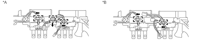
Disengage the 2 wire harnesses of the inverter current sensor sub-assembly from each clamp as shown in the illustration.

HINT:

The number of clamps used to engage the wire harness varies depending on the type of inverter with converter assembly. Confirm the type before performing work.

A330574E02
0.095,0 0.478,0.267 0.383,0.267 10 *A 3.612,0 4.082,0.332 0.471,0.332 10 *B

Text in Illustration
*A For inverter with converter assembly with part number G9200-47160, G9200-47161 or G9200-47162 *B For inverter with converter assembly with part number other than G9200-47160, G9200-47161 or G9200-47162


c.
A326170E01
0.13,0.119 0.460,0.413 0.330,0.295 10 *A 0.113,2.594 0.443,2.888 0.330,0.295 10 *B 2.614,3.591 2.734,2.826 false 2.734,2.826 3.172,2.826 false 2.837,3.591 2.958,2.826 false 3.201,2.731 3.380,2.917 0.179,0.186 10 *a

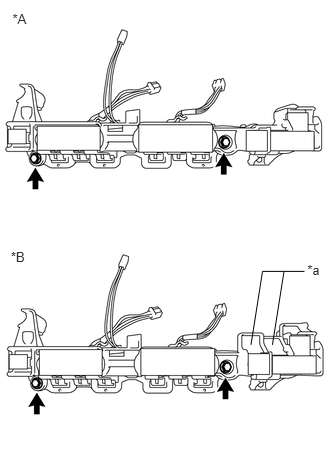
Remove the 2 bolts and inverter current sensor sub-assembly.

NOTICE:

Do not touch the bus-bars.


Text in Illustration
*A Type 1
*B Type 2
*a Terminal Tray


Hide 2.REMOVE INVERTER WIRE SUB-ASSEMBLY

a.

Disengage the wire harness of the inverter wire sub-assembly from each clamp as shown in the illustration.

NOTICE:

Do not pull the wire harness excessively.

A326163E01
4.186,0.124 4.779,0.683 0.593,0.559 10 *A 4.186,1.343 4.779,1.902 0.593,0.559 10 *B 5.545,1.834 5.825,1.455 false 5.825,1.455 6.12,1.455 false 6.141,1.364 6.560,1.729 0.420,0.364 10 *a

Text in Illustration
*A Type 1 *B Type 2
*a Terminal Tray - -


b.

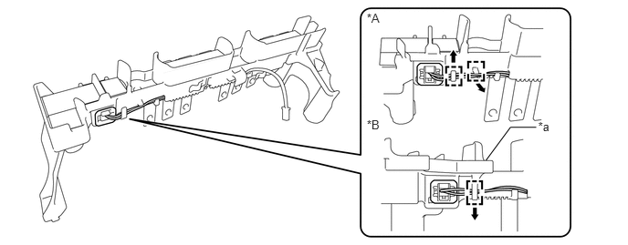
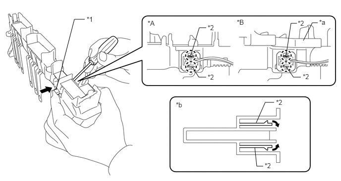
Using a screwdriver, disengage the 2 claws while lightly pushing in the protruding part of the interlock connector (A) as shown in the illustration to disconnect it.
A330571E04
6.375,0.854 6.563,0.479 6.563,0.479 6.677,0.479 false 1.177,1.896 1.563,0.406 1.563,0.406 1.781,0.406 false 4.01,1.167 4.188,0.583 4.188,0.583 4.333,0.583 false 4.042,1.406 4.177,1.625 4.177,1.625 4.333,1.625 false 6.01,1.177 6.115,0.49 6.115,0.49 6.24,0.49 false 6.01,1.396 6.167,1.625 6.167,1.625 6.323,1.625 false 5.385,2.583 5.573,2.156 5.573,2.156 5.76,2.156 false 5.354,3.104 5.396,3.5 5.396,3.5 5.531,3.5 false 3.104,0.406 3.531,0.927 0.427,0.521 10 false *A 4.979,0.385 5.406,0.906 0.427,0.521 10 false *B 6.708,0.385 7.115,0.729 0.406,0.344 10 false *a 3.698,2.125 4.104,2.469 0.406,0.344 10 false *b 1.823,0.323 2.167,0.635 0.344,0.313 10 false *1 6.26,0.406 6.667,0.75 0.406,0.344 10 false *2 4.365,0.5 4.771,0.844 0.406,0.344 10 false *2 4.365,1.542 4.771,1.885 0.406,0.344 10 false *2 6.365,1.531 6.771,1.875 0.406,0.344 10 false *2 5.802,2.073 6.208,2.417 0.406,0.344 10 false *2 5.563,3.406 5.969,3.75 0.406,0.344 10 false *2

Text in Illustration
*A Type 1 *B Type 2
*1 Inter Lock Connector A *2 Claw
*a Terminal Tray *b Cross Section (Inter Lock Connector A)


c.

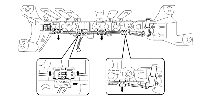
Disengage the wire harness of the inverter wire sub-assembly from the 6 clamps.
A326175


d.

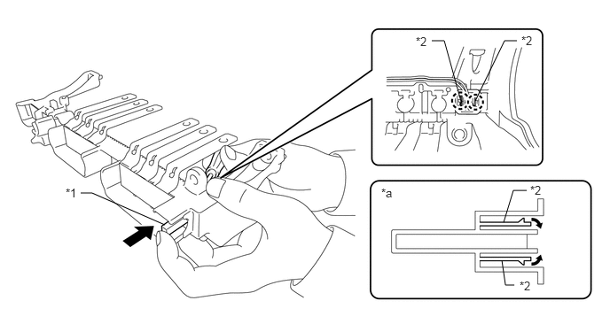
Using a screwdriver, disengage the 2 claws while lightly pushing in the protruding part of the interlock connector (B) as shown in the illustration to disconnect it and remove the inverter wire sub-assembly.
A330570E04
5.583,1.188 5.927,0.479 5.927,0.479 6.073,0.479 false 5.406,1.156 5.219,0.479 5.219,0.479 5.073,0.479 false 5.917,2.615 6.031,2.24 6.031,2.24 6.188,2.24 false 5.896,3.063 5.938,3.354 5.938,3.354 6.042,3.354 false 1.938,2.646 1.083,2.271 1.083,2.271 0.948,2.271 false 4.885,0.406 5.125,0.646 0.24,0.24 10 false *2 6.125,0.396 6.365,0.635 0.24,0.24 10 false *2 6.229,2.156 6.469,2.396 0.24,0.24 10 false *2 6.104,3.281 6.344,3.521 0.24,0.24 10 false *2 0.771,2.188 1.01,2.427 0.24,0.24 10 false *1 4.479,2.188 4.719,2.427 0.24,0.24 10 false *a

Text in Illustration
*1 Inter Lock Connector B *2 Claw
*a Cross Section (Inter Lock Connector B) - -