RM2070E
_51
Engine / Hybrid System
_061908
2ZR-FXE FUEL
_0301605
FUEL SENDER GAUGE ASSEMBLY
G
2ZR-FXE FUEL FUEL SENDER GAUGE ASSEMBLY INSPECTION
PROCEDURE

 83320
1.INSPECT FUEL SENDER GAUGE ASSEMBLY
a.
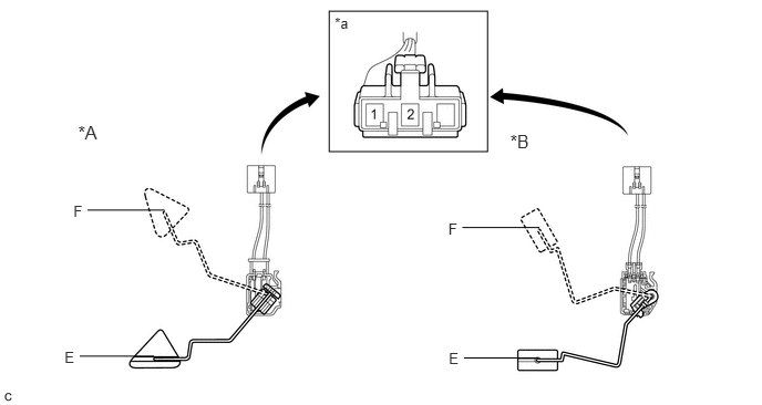
Check that the float moves smoothly between F and E.
b.
Measure the resistance according to the value(s) in the table below.
0.691,1.908 0.821,2.066
0.130,0.158
10
F
0.607,3.279 0.753,3.437
0.146,0.158
10
E
1.548,1.977 0.823,1.977
false
1.448,3.352 0.75,3.352
false
4.217,2.072 4.346,2.230
0.130,0.158
10
F
4.221,3.296 4.367,3.455
0.146,0.158
10
E
5.073,2.141 4.349,2.141
false
5.062,3.369 4.364,3.369
false
3.096,0.105 4.586,1.427
1.49,1.322
3.148,0.14 3.347,0.303
0.199,0.162
10
*a
0.735,1.148 1.051,1.385
0.317,0.238
12
*A
4.798,1.229 5.115,1.467
0.317,0.238
12
*B
| *A | Type A | *B | Type B |
| *a | Component without wire harness connected
(Fuel Sender Gauge Assembly) |
- | - |
- Standard Resistance:
Tester Connection Float Level Type A Type B 1 - 2 F 12.0 to 18.0 Ω 13.5 to 16.5 Ω Between F and E 12.0 to 415.0 Ω (Gradually changes) 13.5 to 414.5 Ω (Gradually changes) E 405.0 to 415.0 Ω 405.5 to 414.5 Ω
If the value is not as specified, replace the fuel sender gauge assembly.