RM2070E
_51
Engine / Hybrid System
_061914
CRUISE CONTROL
_0301639
CRUISE CONTROL SYSTEM
U
CRUISE CONTROL CRUISE CONTROL SYSTEM TERMINALS OF ECU
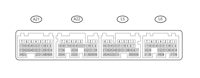
CHECK HYBRID VEHICLE CONTROL ECU
1.177,0.604 1.458,0.781
0.281,0.177
10
false
A21
2.635,0.594 2.979,0.771
0.344,0.177
10
false
A22
4.323,0.594 4.542,0.771
0.219,0.177
10
false
L5
5.677,0.594 5.875,0.771
0.198,0.177
10
false
L6
| Terminal No. (Symbol) | Wiring Color | Terminal Description | Condition | Specified Condition |
|---|---|---|---|---|
| A22-28 (ST1-) - L5-6 (E1) | R - W-B | Stop light switch signal | Power switch on (IG), Brake pedal released | 11 to 14 V |
| A22-28 (ST1-) - L5-6 (E1) | R - W-B | Stop light switch signal | Power switch on (IG), Brake pedal depressed | Below 1 V |
| A21-15 (STP) - L5-6 (E1) | L - W-B | Stop light switch signal | Brake pedal released | Below 1 V |
| A21-15 (STP) - L5-6 (E1) | L - W-B | Stop light switch signal | Brake pedal depressed | 11 to 14 V |
| L5-6 (E1) - Body ground | W-B - Body ground | Earth (ground) circuit of hybrid vehicle control ECU | Always | Below 1 Ω |
| L6-28 (TC) - L5-6 (E1) | P - W-B | Terminal TC of DLC3 | Power switch on (IG) | 11 to 14 V |
| L6-28 (TC) - L5-6 (E1) | P - W-B | Terminal TC of DLC3 | Terminals TC and CG of DLC3 connected | Below 1 V |
| L5-28 (CCS) - L5-6 (E1) | BE - W-B | Cruise control switch circuit | Power switch on (IG) | 1 MΩ or higher |
| L5-28 (CCS) - L5-6 (E1) | BE - W-B | Cruise control switch circuit | Power switch on (IG), Cruise control switch on | Below 2.5 Ω |
| L5-28 (CCS) - L5-6 (E1) | BE - W-B | Cruise control switch circuit | Power switch on (IG), +/RES switch on | 235 to 245 Ω |
| L5-28 (CCS) - L5-6 (E1) | BE - W-B | Cruise control switch circuit | Power switch on (IG), -/SET switch on | 617 to 643 Ω |
| L5-28 (CCS) - L5-6 (E1) | BE - W-B | Cruise control switch circuit | Power switch on (IG), CANCEL switch on | 1509 to 1571 Ω |
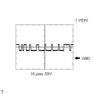
| L6-24 (CA1L) - L5-6 (E1) | P - W-B | CAN communication line | Power switch on (IG) | Pulse generation
(see waveform 1) |
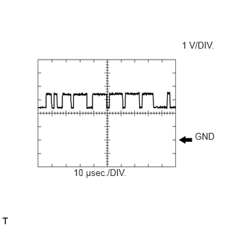
| L6-25 (CA1H) - L5-6 (E1) | V - W-B | CAN communication line | Power switch on (IG) | Pulse generation
(see waveform 2) |
a.
2.99,2.052 3.333,2.219
0.344,0.167
10
false
GND
2.75,0.656 3.354,0.833
0.604,0.177
10
false
1 V/DIV.
1.115,2.615 1.969,2.792
0.854,0.177
10
false
10 μsec./DIV.
WAVEFORM 1
i.
CAN communication signal
| Hybrid Vehicle Control ECU Terminal Name | Between L6-24 (CA1L) and L5-6 (E1) |
| Tester Range | 1 V/DIV., 10 μsec./DIV. |
| Condition | Power switch on (IG) |
- HINT:
-
The waveform varies depending on the CAN communication signal.
b.
2.962,1.99 3.303,2.156
0.341,0.166
10
GND
2.764,0.6 3.298,0.781
0.534,0.181
10
1 V/DIV.
1.117,2.545 1.989,2.726
0.872,0.181
10
10 μsec./DIV.
WAVEFORM 2
i.
CAN communication signal
| Hybrid Vehicle Control ECU Terminal Name | Between L6-25 (CA1H) and L5-6 (E1) |
| Tester Range | 1 V/DIV., 10 μsec./DIV. |
| Condition | Power switch on (IG) |
- HINT:
-
The waveform varies depending on the CAN communication signal.