RM2070E
_51
Engine / Hybrid System
_061914
CRUISE CONTROL
_0301640
DYNAMIC RADAR CRUISE CONTROL SYSTEM
U
CRUISE CONTROL DYNAMIC RADAR CRUISE CONTROL SYSTEM TERMINALS OF ECU
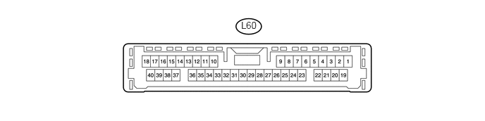
CHECK DRIVING SUPPORT ECU
3.563,0.292 3.844,0.458
0.281,0.167
10
false
L60
| Terminal No. (Symbol) | Wiring Color | Terminal Description | Condition | Specified Condition |
|---|---|---|---|---|
| L60-7 (MODE) - L60-25 (GND) | R - W-B | Steering pad switch signal
(distance control signal) |
Power switch on (IG)
Distance control switch off |
11 to 14 V |
| L60-7 (MODE) - L60-25 (GND) | R - W-B | Steering pad switch signal
(distance control signal) |
Power switch on (IG)
Distance control switch on |
Below 2 V |
| L60-10 (CCHG) - L60-25 (GND) | G - W-B | Cruise control switch signal | Power switch on (IG),
MODE switch off |
11 to 14 V |
| L60-10 (CCHG) - L60-25 (GND) | G - W-B | Cruise control switch signal | Power switch on (IG),
MODE switch on |
Below 2 V |
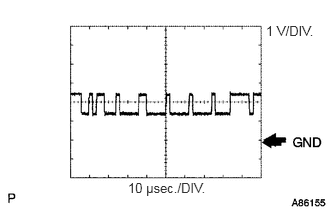
| L60-17 (CA2L) - L60-25 (GND) | R - W-B | CAN communication signal | Power switch on (IG) | Pulse generation
(See waveform 1) |
| L60-23 (CCS) - L60-25 (GND) | V - W-B | Cruise control switch signal | Power switch on (IG) | 1 MΩ or higher |
| L60-23 (CCS) - L60-25 (GND) | V - W-B | Cruise control switch signal | CANCEL switch on | 1509 to 1571 Ω |
| L60-23 (CCS) - L60-25 (GND) | V - W-B | Cruise control switch signal | -/SET switch on | 617 to 643 Ω |
| L60-23 (CCS) - L60-25 (GND) | V - W-B | Cruise control switch signal | +/RES switch on | 235 to 245 Ω |
| L60-23 (CCS) - L60-25 (GND) | V - W-B | Cruise control switch signal | Cruise control switch on | Below 2.5 Ω |
| L60-25 (GND) - Body ground | W-B - Body ground | Earth (ground circuit of driving support ECU) | Always | Below 1 Ω |
| L60-27 (STP-) - L60-25 (GND) | Y - W-B | Stop light signal | Brake pedal released | Below 1 V |
| L60-27 (STP-) - L60-25 (GND) | Y - W-B | Stop light signal | Brake pedal depressed | 11 to 14 V |
| L60-28 (ST1-) - L60-25 (GND) | V - W-B | Stop light signal | Power switch on (IG),
Brake pedal released |
11 to 14 V |
| L60-28 (ST1-) - L60-25 (GND) | V - W-B | Stop light signal | Power switch on (IG),
Brake pedal depressed |
Below 1 V |
| L60-30 (B) - L60-25 (GND) | B - W-B | Power source | Power switch on (IG) | 11 to 14 V |
| L60-32 (WIP2) - L60-25 (GND) | P - W-B | Wiper switch signal | Power switch on (IG),
Wiper switch off |
Below 2.4 V |
| L60-32 (WIP2) - L60-25 (GND) | P - W-B | Wiper switch signal | Power switch on (IG),
Wiper switch HI position |
11 to 14 V |
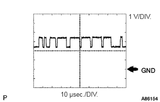
| L60-39 (CA2H) - L60-25 (GND) | B - W-B | CAN communication signal | Power switch on (IG) | Pulse generation
(See waveform 2) |
a.
2.771,0.24 3.313,0.438
0.542,0.198
10
false
1 V/DIV.
1.333,1.875 2.198,2.052
0.865,0.177
10
false
10 μsec./DIV.
WAVEFORM 1
i.
CAN communication signal
| Driving support ECU Terminal Name | Between L60-17 (CA2L) and L60-25 (GND) |
| Tester Range | 1 V/DIV., 10 μsec./DIV. |
| Condition | Power switch on (IG) |
- HINT:
-
The waveform varies depending on the CAN communication signal.
b.
2.76,0.271 3.302,0.469
0.542,0.198
10
false
1 V/DIV.
1.302,1.938 2.156,2.104
0.854,0.167
10
false
10 μsec./DIV.
WAVEFORM 2
i.
CAN communication signal
| Driving support ECU Terminal Name | Between L60-39 (CA2H) and L60-25 (GND) |
| Tester Range | 1 V/DIV., 10 μsec./DIV. |
| Condition | Power switch on (IG) |
- HINT:
-
The waveform varies depending on the CAN communication signal.