P410 HYBRID TRANSMISSION / TRANSAXLE ELECTRONIC SHIFT LEVER SYSTEM C2315 HV System
DESCRIPTION
The transmission control ECU assembly receives a P position switch signal from the hybrid vehicle control ECU and activates the parking lock motor by controlling current, causing the parking lock mechanism to switch. When the hybrid vehicle control ECU detects a malfunction with the P position switch (transmission shift main switch) or P position signal, it sends an information signal to the transmission control ECU assembly. After receiving this signal, the transmission control ECU assembly stores this DTC.
| DTC No. | DTC Detection Condition | Trouble Area |
|---|---|---|
| C2315 | With the power switch on (IG) (IG circuit malfunction is not detected), a malfunction signal is received from the hybrid vehicle control ECU for 2 seconds or more. | Hybrid vehicle control ECU |
WIRING DIAGRAM
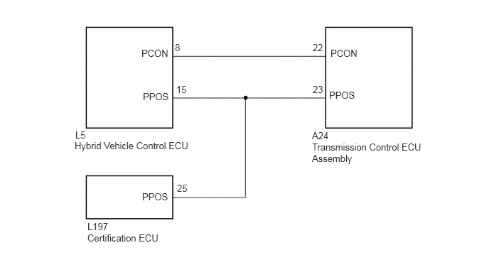
PROCEDURE
Connect the GTS to the DLC3.
Turn the power switch on (IG).
Enter the following menus: Powertrain / Hybrid Control / Trouble Codes.
Check if DTCs are output.
- Result:
Result Proceed to The following DTCs are not output. A Any of the following DTCs are output. B
| DTC No. | Relevant Diagnosis |
|---|---|
| P0851-579 | Park/Neutral Switch Input Circuit Low |
| P0852-580 | Park/Neutral Switch Input Circuit High |
| P085D-599 | Gear Shift Control Module "A" Performance |
| P0861-597 | Gear Shift Control Module "A" Communication Circuit Low |
| P0862-598 | Gear Shift Control Module "A" Communication Circuit High |
| U1107-436 | Lost Communication with Power Management Module |
Turn the power switch off.
A
B
(See pageEngine / Hybrid System>HYBRID / BATTERY CONTROL>HYBRID CONTROL SYSTEM>DIAGNOSTIC TROUBLE CODE CHART)
Connect the GTS to the DLC3.
Turn the power switch on (IG).
Enter the following menus: Body Electrical / Transmission Control / Trouble Codes.
Read and record the DTCs and freeze frame data.
Clear DTCs and freeze frame data.
Turn the power switch off.
NEXT
Connect the GTS to the DLC3.
Turn the power switch on (IG).
Wait for 2 seconds or more.
Enter the following menus: System Select / Health Check.
Check if DTCs are output.
- Result:
Result Proceed to DTC is not output. A DTC C2315 only is output. B DTC C2315 and other DTCs are output together. C
- HINT:
-
DTC C2315 only may be output when the P position switch (transmission shift main switch) connector is disconnected and reconnected.
Turn the power switch off.
A
B
C