RM2070E
_53
Suspension
_061921
TIRE PRESSURE MONITORING
_0301678
TIRE PRESSURE WARNING SYSTEM
J
TIRE PRESSURE MONITORING TIRE PRESSURE WARNING SYSTEM TC and CG Terminal Circuit
DESCRIPTION
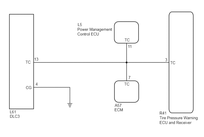
Tire pressure warning system DTCs can be checked by connecting terminals 13 (TC) and 4 (CG) of the DLC3. The DTCs are indicated by blinking the tire pressure warning light.
WIRING DIAGRAM
0.344,3.854 0.625,4
0.281,0.146
10
false
L61
0.344,4.01 0.75,4.177
0.406,0.167
10
false
DLC3
0.896,2.104 1.115,2.26
0.219,0.156
10
false
TC
4.365,2.875 4.583,3.031
0.219,0.156
10
false
TC
5.979,2.125 6.198,2.281
0.219,0.156
10
false
TC
0.906,3 1.167,3.219
0.26,0.219
10
false
CG
1.198,2 1.406,2.208
0.208,0.208
10
false
13
1.25,2.875 1.375,3.073
0.125,0.198
10
false
4
4.49,1.552 4.688,1.719
0.198,0.167
10
false
11
5.802,2.021 5.917,2.177
0.115,0.156
10
false
3
4.021,3.781 4.375,3.938
0.354,0.156
10
false
ECM
5.604,4.063 7,4.542
1.396,0.479
10
false
Tire Pressure Warning ECU and Receiver
5.604,3.896 5.917,4.094
0.313,0.198
10
false
R41
4.51,2.646 4.708,2.813
0.198,0.167
10
false
7
4.031,3.625 4.313,3.781
0.281,0.156
10
false
A57
2.729,0.781 3.01,0.938
0.281,0.156
10
false
L5
4.375,1.323 4.594,1.479
0.219,0.156
10
false
TC
2.719,0.948 3.948,1.354
1.229,0.406
10
false
Power Management Control ECU
PROCEDURE
1.CHECK HARNESS AND CONNECTOR (TC of DLC3 - TIRE PRESSURE WARNING ECU AND RECEIVER, ECM AND POWER MANAGEMENT CONTROL ECU)
a.
Disconnect the R41 tire pressure warning ECU and receiver connector.
b.
Disconnect the A57 ECM connector.
c.
Disconnect the L5 power management control ECU connector.
d.
Measure the resistance according to the value(s) in the table below.
- Standard Resistance:
Tester Connection Condition Specified Condition R41-3 (TC) - L61-13 (TC) Always Below 1 Ω R41-3 (TC), A57-7 (TC), L5-11 (TC) or L61-13 (TC) - Body ground Always 10 kΩ or higher
OK
2.CHECK HARNESS AND CONNECTOR (CG of DLC3 - BODY GROUND)
NG
REPAIR OR REPLACE HARNESS OR CONNECTOR
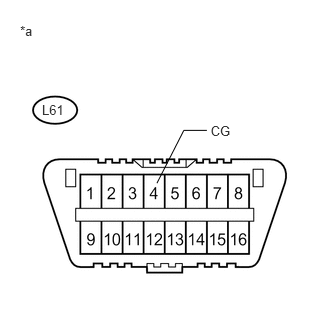
2.CHECK HARNESS AND CONNECTOR (CG of DLC3 - BODY GROUND)
a.
0.437,1.064 0.779,1.219
0.343,0.156
10
L61
0.209,0.244 0.364,0.399
0.154,0.156
10
*a
2.194,1.278 2.543,1.434
0.349,0.156
10
CG
1.634,1.908 1.914,1.358
1.914,1.358 2.154,1.358
false
Measure the resistance according to the value(s) in the table below.
- Standard Resistance:
Tester Connection Condition Specified Condition L61-4 (CG) - Body ground Always Below 1 Ω
| *a | Front view of DLC3 |
OK
PROCEED TO NEXT SUSPECTED AREA SHOWN IN PROBLEM SYMPTOMS TABLE
NG
REPAIR OR REPLACE HARNESS OR CONNECTOR