BRAKE CONTROL / DYNAMIC CONTROL SYSTEMS FRONT SPEED SENSOR INSTALLATION
CAUTION / NOTICE / HINT
- HINT:
- ·
Use the same procedure for the LH side and RH side.
·The following procedure is for the LH side.
·If the sensor rotor needs to be replaced, replace the front axle hub sub-assembly.
PROCEDURE

 89543
1.INSTALL FRONT SPEED SENSOR
Install the front speed sensor with the bolt.
- Torque:
- 8.5 N*m (87 kgf*cm, 75 in.*lbf)
- NOTICE:
- ·
Prevent foreign matter from attaching to the front speed sensor tip.
·Firmly insert the front speed sensor body into the knuckle before tightening the bolt.
·After installing the front speed sensor to the knuckle, make sure that there is no clearance between the front speed sensor stay and knuckle. Also make sure that no foreign matter is stuck between the parts.
·Before installing the clamp, firmly insert the points of the clamp into the installation holes.
Install the clamp to the front shock absorber assembly.
Set the front flexible hose to the front shock absorber assembly.
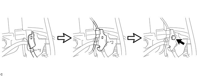
| *1 | Front Flexible Hose | *2 | No. 1 Sensor Clamp |
Install the front flexible hose and No. 1 sensor clamp together to the front shock absorber assembly with the bolt.
- Torque:
- 19 N*m (192 kgf*cm, 14 ft.*lbf)
- NOTICE:
- ·
Do not twist the wire harness for the front speed sensor when installing the speed sensor.
·The bolt tightens the brake flexible hose and front speed sensor together. Make sure that the front speed sensor is positioned over the front brake flexible hose.
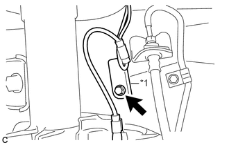
Install the No. 2 sensor clamp to the body with the bolt.
| *1 | No. 2 Sensor Clamp |
- Torque:
- 8.5 N*m (87 kgf*cm, 75 in.*lbf)
Connect the speed sensor connector.
Install the 2 speed sensor wire harness clamps to the body.
53876A
2.INSTALL FRONT FENDER LINER
- HINT:
-
Use the same procedure for the LH side and RH side (See page Vehicle Exterior>WIPER / WASHER>WASHER MOTOR(for Front Side)>INSTALLATION).
3.CONNECT CABLE TO NEGATIVE AUXILIARY BATTERY TERMINAL
4.CHECK FOR SPEED SENSOR SIGNAL