Home › Audio / Visual / Telematics › AUDIO / VIDEO › AUDIO AND VISUAL SYSTEM › 2016.05–2020.08
RM2070E _56 Audio / Visual / Telematics _061931 AUDIO / VIDEO _0301730 AUDIO AND VISUAL SYSTEM J

AUDIO / VIDEO  AUDIO AND VISUAL SYSTEM  Reverse Signal Circuit  


DESCRIPTION

The radio and display receiver assembly receives a reverse signal from the power management control ECU via the No. 1 integration relay.

WIRING DIAGRAM
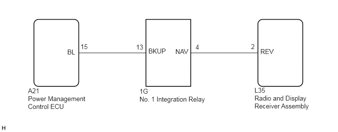
E230082E24
3.146,1 3.688,1.208 0.542,0.208 10 false BKUP 0.594,1.844 0.885,2.052 0.292,0.208 10 false A21 2.958,1.854 3.25,2.063 0.292,0.208 10 false 1G 5.396,1.833 5.854,2.042 0.458,0.208 10 false L35 5.396,2 6.615,2.354 1.219,0.354 10 false Radio and Display Receiver Assembly 2.958,2.021 4.604,2.167 1.646,0.146 10 false No. 1 Integration Relay 0.594,2.01 1.896,2.406 1.302,0.396 10 false Power Management Control ECU 2.885,0.917 3.083,1.073 0.198,0.156 10 false 13 4.146,0.917 4.281,1.073 0.135,0.156 10 false 4 5.323,0.906 5.448,1.063 0.125,0.156 10 false 2 5.521,1.01 5.885,1.219 0.365,0.208 10 false REV 3.719,1.01 4.083,1.219 0.365,0.208 10 false NAV 1.427,1.021 1.625,1.188 0.198,0.167 10 false BL 1.708,0.906 1.917,1.083 0.208,0.177 10 false 15

PROCEDURE

1.INSPECT RADIO AND DISPLAY RECEIVER ASSEMBLY
a.

Disconnect the L35 radio and display receiver assembly connector.


b.

Measure the voltage according to the value(s) in the table below.

Standard Voltage:
Tester Connection Condition Specified Condition
L35-2 (REV) - Body ground Power switch on (READY)
Reverse (R) selected
11 to 15.5 V
L35-2 (REV) - Body ground Power switch on (READY)
Reverse (R) not selected
Below 1 V


OK

PROCEED TO NEXT SUSPECTED AREA SHOWN IN PROBLEM SYMPTOMS TABLE

NG

2.CHECK HARNESS AND CONNECTOR (RADIO AND DISPLAY RECEIVER ASSEMBLY - NO. 1 INTEGRATION RELAY)
a.

Disconnect the L35 radio and display receiver assembly connector.


b.

Disconnect the 1G No. 1 integration relay connector.


c.

Measure the resistance according to the value(s) in the table below.

Standard Resistance:
Tester Connection Condition Specified Condition
L35-2 (REV) - 1G-4 (NAV) Always Below 1 Ω
L35-2 (REV) - Body ground Always 10 kΩ or higher


OK

3.CHECK HARNESS AND CONNECTOR (NO. 1 INTEGRATION RELAY - POWER MANAGEMENT CONTROL ECU)

NG

REPAIR OR REPLACE HARNESS OR CONNECTOR

3.CHECK HARNESS AND CONNECTOR (NO. 1 INTEGRATION RELAY - POWER MANAGEMENT CONTROL ECU)
a.

Disconnect the 1G No. 1 integration relay connector.


b.

Disconnect the A21 power management control ECU connector.


c.

Measure the resistance according to the value(s) in the table below.

Standard Resistance:
Tester Connection Condition Specified Condition
1G-13 (BKUP) - A21-15 (BL) Always Below 1 Ω
1G-13 (BKUP) - Body ground Always 10 kΩ or higher


OK

4.REPLACE NO. 1 INTEGRATION RELAY

NG

REPAIR OR REPLACE HARNESS OR CONNECTOR

4.REPLACE NO. 1 INTEGRATION RELAY
a.

Replace the No. 1 integration relay with a new or known good one (See page Power Source / Network>POWER DISTRIBUTION>INTEGRATION RELAY>REMOVAL).


b.

Check that the malfunction disappears.

OK:

Malfunction disappears.


OK

END (NO. 1 INTEGRATION RELAY WAS DEFECTIVE)

NG

REPLACE POWER MANAGEMENT CONTROL ECU