RM2070E
_56
Audio / Visual / Telematics
_061932
NAVIGATION / MULTI INFO DISPLAY
_0301737
NAVIGATION SYSTEM
J
NAVIGATION / MULTI INFO DISPLAY NAVIGATION SYSTEM Sound Signal Circuit between Navigation Receiver Assembly and Stereo Component Amplifier
DESCRIPTION
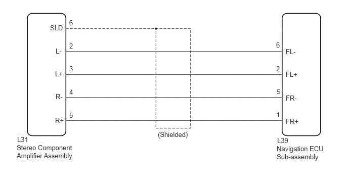
The navigation ECU sub-assembly sends a sound signal to the stereo component amplifier assembly via this circuit.
The sound signal that has been sent is amplified by the stereo component amplifier assembly, and then is sent to the speakers.
If there is an open or short in the circuit, sound cannot be heard from the speakers even if there is no malfunction in the stereo component amplifier assembly or speakers.
WIRING DIAGRAM
1.146,0.969 1.292,1.125
0.146,0.156
10
false
L-
1.135,1.438 1.313,1.594
0.177,0.156
10
false
L+
1.146,1.906 1.354,2.063
0.208,0.156
10
false
R-
1.135,2.396 1.354,2.563
0.219,0.167
10
false
R+
1.427,0.865 1.615,1.031
0.188,0.167
10
false
2
1.427,1.333 1.615,1.5
0.188,0.167
10
false
3
1.427,1.813 1.615,1.979
0.188,0.167
10
false
4
1.427,2.292 1.615,2.458
0.188,0.167
10
false
5
5.688,0.844 5.802,1.01
0.115,0.167
10
false
6
5.688,1.333 5.792,1.5
0.104,0.167
10
false
2
5.688,2.281 5.792,2.448
0.104,0.167
10
false
1
5.698,1.802 5.813,1.969
0.115,0.167
10
false
5
5.885,0.979 6.219,1.135
0.333,0.156
10
false
FL-
5.885,1.448 6.219,1.604
0.333,0.156
10
false
FL+
5.885,1.938 6.219,2.094
0.333,0.156
10
false
FR-
5.885,2.417 6.219,2.573
0.333,0.156
10
false
FR+
5.708,2.813 6.146,2.99
0.438,0.177
10
false
L39
5.698,2.979 6.719,3.479
1.021,0.5
10
false
Navigation ECU Sub-assembly
0.354,2.792 0.75,2.958
0.396,0.167
10
false
L31
0.344,2.958 1.542,3.323
1.198,0.365
10
false
Stereo Component Amplifier Assembly
3.25,2.688 4.063,2.938
0.813,0.25
10
false
(Shielded)
1.031,0.49 1.375,0.646
0.344,0.156
10
false
SLD
1.427,0.385 1.615,0.552
0.188,0.167
10
false
6
PROCEDURE
1.CHECK HARNESS AND CONNECTOR (NAVIGATION ECU SUB-ASSEMBLY - STEREO COMPONENT AMPLIFIER ASSEMBLY)
a.
Disconnect the L39 navigation ECU sub-assembly connector.
b.
Disconnect the L31 stereo component amplifier assembly connector.
c.
Measure the resistance according to the value(s) in the table below.
- Standard Resistance:
Tester Connection Condition Specified Condition L31-5 (R+) - L39-1 (FR+) Always Below 1 Ω L31-4 (R-) - L39-5 (FR-) Always Below 1 Ω L31-3 (L+) - L39-2 (FL+) Always Below 1 Ω L31-2 (L-) - L39-6 (FL-) Always Below 1 Ω L31-6 (SLD) - Body ground Always 10 kΩ or higher L31-5 (R+) - Body ground Always 10 kΩ or higher L31-4 (R-) - Body ground Always 10 kΩ or higher L31-3 (L+) - Body ground Always 10 kΩ or higher L31-2 (L-) - Body ground Always 10 kΩ or higher
OK
PROCEED TO NEXT SUSPECTED AREA SHOWN IN PROBLEM SYMPTOMS TABLE
(See pageAudio / Visual / Telematics>NAVIGATION / MULTI INFO DISPLAY>NAVIGATION SYSTEM>PROBLEM SYMPTOMS TABLE)
NG
REPAIR OR REPLACE HARNESS OR CONNECTOR