RM2070E
_56
Audio / Visual / Telematics
_061932
NAVIGATION / MULTI INFO DISPLAY
_0301740
NAVIGATION SYSTEM(for Navigation Receiver Type)
J
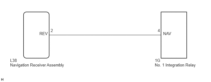
NAVIGATION / MULTI INFO DISPLAY NAVIGATION SYSTEM(for Navigation Receiver Type) Reverse Signal Circuit
DESCRIPTION
The navigation receiver assembly receives a reverse signal from the No. 1 integration relay.
WIRING DIAGRAM
5.259,1.979 5.595,2.149
0.336,0.170
10
1G
5.259,2.133 6.789,2.317
1.530,0.184
10
No. 1 Integration Relay
0.344,2.133 2.785,2.329
2.441,0.197
10
Navigation Receiver Assembly
1.339,1.066 1.786,1.251
0.448,0.185
10
REV
5.542,1.066 5.996,1.258
0.455,0.193
10
NAV
0.344,1.979 0.646,2.149
0.302,0.170
10
L38
5.354,0.961 5.592,1.128
0.238,0.166
10
4
1.721,0.961 1.933,1.110
0.211,0.149
10
2
PROCEDURE
1.CHECK BACK-UP LIGHT
a.
Check that the back-up light comes on.
- OK:
The back-up light comes on.
OK
2.CHECK HARNESS AND CONNECTOR (REVERSE SIGNAL)
NG
GO TO LIGHTING SYSTEM
2.CHECK HARNESS AND CONNECTOR (REVERSE SIGNAL)
a.
Disconnect the L38 navigation receiver assembly connector.
b.
Measure the voltage according to the value(s) in the table below.
- Standard Voltage:
Tester Connection Condition Specified Condition L38-2 (REV) - Body ground Power switch on (IG)
Reverse (R) selected11 to 14 V L38-2 (REV) - Body ground Power switch on (IG)
Shift state other than reverse (R) selectedBelow 1 V
OK
PROCEED TO NEXT SUSPECTED AREA SHOWN IN PROBLEM SYMPTOMS TABLE
NG
REPAIR OR REPLACE HARNESS OR CONNECTOR