Home › Power Source / Network › NETWORKING › CAN COMMUNICATION SYSTEM (w/o Central Gateway ECU) › 2014.11–2016.05
RM2070E _57 Power Source / Network _061936 NETWORKING _0301754 CAN COMMUNICATION SYSTEM(w/o Central Gateway ECU) U

NETWORKING  CAN COMMUNICATION SYSTEM(w/o Central Gateway ECU)  SYSTEM DIAGRAM  


OVERALL CAN BUS DIAGRAM (for LHD)


a.

The CAN communication system is composed of 4 buses.
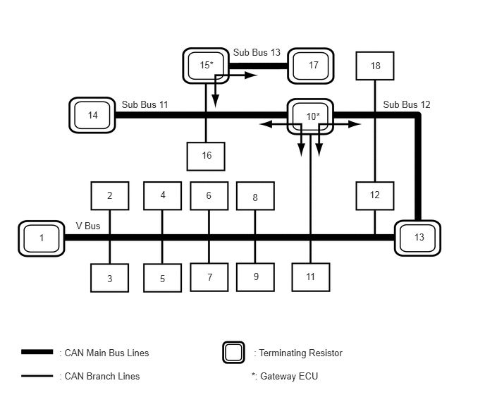
C316695E01
1.121,3.251 1.558,3.433 0.437,0.183 10 V Bus 1.798,1.463 2.624,1.645 0.826,0.183 10 Sub Bus 11 5.66,1.463 6.486,1.645 0.826,0.183 10 Sub Bus 12 3.444,0.692 4.271,0.875 0.826,0.183 10 Sub Bus 13 0.577,3.431 0.679,3.587 0.102,0.156 10 1 1.584,2.803 1.686,2.959 0.102,0.156 10 2 2.369,2.793 2.470,2.949 0.102,0.156 10 4 3.047,2.8 3.149,2.956 0.102,0.156 10 6 3.065,4.014 3.167,4.169 0.102,0.156 10 7 3.748,4 3.849,4.155 0.102,0.156 10 9 4.517,3.999 4.693,4.155 0.176,0.156 10 11 3.733,2.829 3.835,2.984 0.102,0.156 10 8 4.522,1.639 4.829,1.795 0.308,0.156 10 10* 5.461,2.791 5.634,2.946 0.173,0.156 10 12 1.294,1.615 1.467,1.771 0.173,0.156 10 14 2.948,0.872 3.246,1.027 0.298,0.156 10 15* 2.979,2.205 3.152,2.361 0.173,0.156 10 16 4.558,0.879 4.730,1.035 0.173,0.156 10 17 5.472,0.886 5.645,1.042 0.173,0.156 10 18 6.119,3.421 6.291,3.577 0.173,0.156 10 13 2.363,4.028 2.465,4.184 0.102,0.156 10 5 1.584,4.035 1.686,4.190 0.102,0.156 10 3 0.877,5.12 2.307,5.280 1.429,0.159 10 : CAN Main Bus Lines 0.877,5.471 2.162,5.630 1.285,0.159 10 : CAN Branch Lines 3.752,5.12 5.380,5.280 1.628,0.159 10 : Terminating Resistor 3.715,5.471 4.934,5.630 1.219,0.159 10 *: Gateway ECU

Text in Illustration
1 Combination Meter Sub-assembly
(for V Bus)
2 Main Body ECU (Multiplex Network Body ECU)
(for V Bus)
3 DLC3
(for V Bus)
4 Airbag ECU Assembly
(for V Bus)
5 Spiral Cable with Sensor Sub-assembly (Steering Angle Sensor)
(for V Bus)
6 Radio and Display Receiver Assembly
(for Radio and Display Type)
(for V Bus)
7 Certification ECU (Smart Key ECU Assembly)
(for V Bus)
8 Yaw Rate Sensor
(for V Bus)
9 Power Steering ECU Assembly
(for V Bus)
10 Power Management Control ECU
(for V Bus, Sub Bus 11 and Sub Bus 12)
11 Transmission Control ECU Assembly
(for V Bus)
12 Brake Booster with Master Cylinder Assembly (Skid Control ECU)
(for V Bus and Sub Bus 12)
13 ECM
(for V Bus and Sub Bus 12)
14 CAN No. 1 Junction Terminal
(for Sub Bus 11)
15 Driving Support ECU Assembly
(w/ Pre-crash Safety System)
(for Sub Bus 11 and Sub Bus 13)
16 Parking Assist ECU
(w/ Intelligent Parking Assist System)
(for Sub Bus 11)
17 Millimeter Wave Radar Sensor Assembly
(w/ Pre-crash Safety System)
(for Sub Bus 13)
18 Air Conditioning Amplifier Assembly
(for Sub Bus 12)

HINT:
·

The power management control ECU functions as a gateway between the V bus and sub bus 11, and the V bus and sub bus 12.

·

The driving support ECU assembly functions as a gateway between the sub bus 11 and sub bus 13.

·

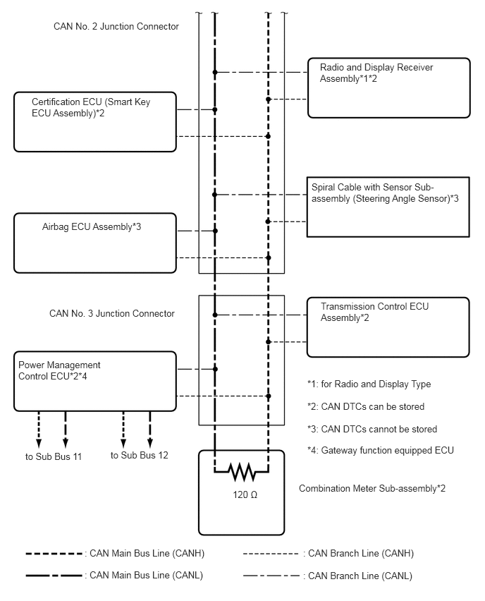
Refer to the following bus wiring diagrams for details.


V BUS (for LHD)
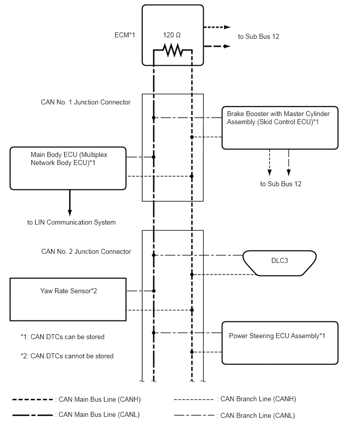

C264997E05
0.635,3.104 2.323,3.552 1.688,0.448 10 false Main Body ECU (Multiplex Network Body ECU)*1 3.365,0.635 4.063,0.865 0.698,0.229 10 false 120 Ω 5.604,5.292 6.177,5.625 0.573,0.333 10 false DLC3 4.688,2.26 7.052,2.802 2.365,0.542 10 false Brake Booster with Master Cylinder Assembly (Skid Control ECU)*1 4.729,6.844 6.906,7.229 2.177,0.385 10 false Power Steering ECU Assembly*1 4.917,0.667 6.74,0.938 1.823,0.271 10 false to Sub Bus 12 1.135,8.156 3.094,8.479 1.958,0.323 10 false : CAN Main Bus Line (CANH) 4.479,8.146 6.188,8.469 1.708,0.323 10 false : CAN Branch Line (CANH) 4.479,8.49 6.167,8.813 1.688,0.323 10 false : CAN Branch Line (CANL) 1.135,8.469 3.094,8.792 1.958,0.323 10 false : CAN Main Bus Line (CANL) 0.844,2.021 2.813,2.323 1.969,0.302 10 false CAN No. 1 Junction Connector 2.365,0.635 2.99,0.927 0.625,0.292 10 false ECM*1 5.375,3.708 6.333,3.979 0.958,0.271 10 false to Sub Bus 12 0.833,5.917 2.156,6.167 1.323,0.25 10 false Yaw Rate Sensor*2 0.854,5.104 2.823,5.406 1.969,0.302 10 false CAN No. 2 Junction Connector 0.427,6.865 2.396,7.167 1.969,0.302 10 false *1: CAN DTCs can be stored 0.427,7.26 3.042,7.656 2.615,0.396 10 false *2: CAN DTCs cannot be stored 0.563,4.5 2.885,4.74 2.323,0.24 10 false to LIN Communication System

C318459E02
0.625,3.26 2.5,3.49 1.875,0.229 10 false Airbag ECU Assembly*3 3.438,7.219 4.135,7.448 0.698,0.229 10 false 120 Ω 4.604,2.677 6.833,3.031 2.229,0.354 10 false Spiral Cable with Sensor Sub-assembly (Steering Angle Sensor)*3 4.417,7.125 6.844,7.417 2.427,0.292 10 false Combination Meter Sub-assembly*2 1.25,8.083 3.208,8.406 1.958,0.323 10 false : CAN Main Bus Line (CANH) 4.479,8.083 6.188,8.406 1.708,0.323 10 false : CAN Branch Line (CANH) 4.479,8.417 6.167,8.74 1.688,0.323 10 false : CAN Branch Line (CANL) 1.25,8.406 3.208,8.729 1.958,0.323 10 false : CAN Main Bus Line (CANL) 0.792,0.302 2.76,0.604 1.969,0.302 10 false CAN No. 2 Junction Connector 0.469,1.417 2.354,1.99 1.885,0.573 10 false Certification ECU (Smart Key ECU Assembly)*2 0.729,4.542 2.698,4.844 1.969,0.302 10 false CAN No. 3 Junction Connector 0.271,5.302 1.719,5.729 1.448,0.427 10 false Power Management Control ECU*2*4 0.375,6.656 1.323,6.958 0.948,0.302 10 false to Sub Bus 11 1.635,6.635 2.615,6.938 0.979,0.302 10 false to Sub Bus 12 4.74,4.438 6.896,5.104 2.156,0.667 10 false Transmission Control ECU Assembly*2 4.729,0.906 6.604,1.333 1.875,0.427 10 false Radio and Display Receiver Assembly*1*2 4.542,5.583 6.74,5.875 2.198,0.292 10 false *1: for Radio and Display Type 4.542,5.917 6.74,6.208 2.198,0.292 10 false *2: CAN DTCs can be stored 4.542,6.25 6.74,6.542 2.198,0.292 10 false *3: CAN DTCs cannot be stored 4.542,6.563 6.906,6.854 2.365,0.292 10 false *4: Gateway function equipped ECU


HINT:

The CAN communication system connects to other networks via ECUs that function as a gateway (See page Power Source / Network>NETWORKING>LIN COMMUNICATION SYSTEM>SYSTEM DIAGRAM).


OVERALL CAN BUS DIAGRAM (for RHD)


a.

The CAN communication system is composed of 4 buses.
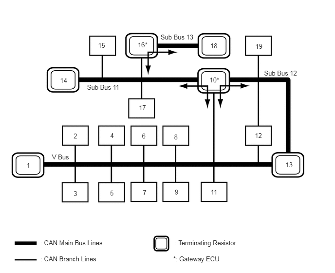
C316696E02
1.112,3.27 1.549,3.452 0.437,0.183 10 V Bus 1.863,1.78 2.689,1.963 0.826,0.183 10 Sub Bus 11 5.651,1.481 6.477,1.664 0.826,0.183 10 Sub Bus 12 3.435,0.711 4.261,0.893 0.826,0.183 10 Sub Bus 13 0.568,3.449 0.670,3.605 0.102,0.156 10 1 1.575,2.822 1.677,2.978 0.102,0.156 10 2 2.359,2.812 2.461,2.968 0.102,0.156 10 4 3.038,2.819 3.139,2.975 0.102,0.156 10 6 3.056,4.032 3.158,4.188 0.102,0.156 10 7 3.738,4.018 3.840,4.174 0.102,0.156 10 9 4.508,4.018 4.684,4.174 0.176,0.156 10 11 3.724,2.847 3.826,3.003 0.102,0.156 10 8 4.484,1.629 4.792,1.785 0.308,0.156 10 10* 5.452,2.809 5.625,2.965 0.173,0.156 10 12 1.285,1.634 1.458,1.789 0.173,0.156 10 14 2.098,0.89 2.396,1.046 0.298,0.156 10 15 2.97,2.224 3.143,2.380 0.173,0.156 10 17 4.499,0.898 4.797,1.054 0.298,0.156 10 18 5.462,0.905 5.635,1.061 0.173,0.156 10 19 6.109,3.44 6.282,3.596 0.173,0.156 10 13 2.354,4.047 2.455,4.203 0.102,0.156 10 5 1.575,4.053 1.677,4.209 0.102,0.156 10 3 0.868,5.102 2.297,5.261 1.429,0.159 10 : CAN Main Bus Lines 0.868,5.452 2.153,5.611 1.285,0.159 10 : CAN Branch Lines 3.742,5.102 5.371,5.261 1.628,0.159 10 : Terminating Resistor 3.706,5.452 4.925,5.611 1.219,0.159 10 *: Gateway ECU 2.948,0.878 3.246,1.034 0.298,0.156 10 16*

Text in Illustration
1 Combination Meter Sub-assembly
(for V Bus)
2 Main Body ECU (Multiplex Network Body ECU)
(for V Bus)
3 DLC3
(for V Bus)
4 Airbag ECU Assembly
(for V Bus)
5 Spiral Cable with Sensor Sub-assembly (Steering Angle Sensor)
(for V Bus)
6
·

Navigation Receiver Assembly

(for Navigation Receiver Type)

·

Radio and Display Receiver Assembly

(for Radio and Display Type)


(for V Bus)
7 Certification ECU (Smart Key ECU Assembly)
(for V Bus)
8 Yaw Rate Sensor
(for V Bus)
9 Power Steering ECU Assembly
(for V Bus)
10 Power Management Control ECU
(for V Bus, Sub Bus 11 and Sub Bus 12)
11 Transmission Control ECU Assembly
(for V Bus)
12 Brake Booster with Master Cylinder Assembly (Skid Control ECU)
(for V Bus and Sub Bus 12)
13 ECM
(for V Bus and Sub Bus 12)
14 CAN No. 1 Junction Terminal
(for Sub Bus 11)
15 Lane Departure Warning Camera
(w/ Lane Departure Alert System)
(for Sub Bus 11)
16 Driving Support ECU Assembly
(w/ Pre-crash Safety System)
(for Sub Bus 11 and Sub Bus 13)
17 Parking Assist ECU
(w/ Intelligent Parking Assist System)
(for Sub Bus 11)
18 Millimeter Wave Radar Sensor Assembly
(w/ Pre-crash Safety System)
(for Sub Bus 13)
19 Air Conditioning Amplifier Assembly
(for Sub Bus 12)
- -

HINT:
·

The power management control ECU functions as a gateway between the V bus and sub bus 11, and the V bus and sub bus 12.

·

The driving support ECU assembly functions as a gateway between the sub bus 11 and sub bus 13.

·

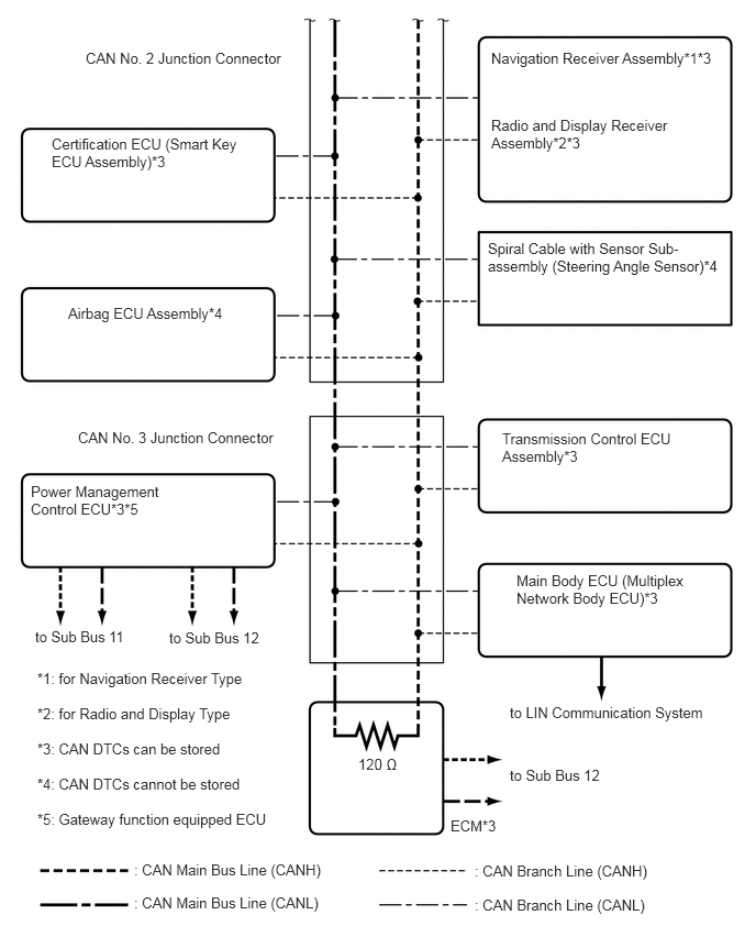
Refer to the following bus wiring diagrams for details.


V BUS (for RHD)
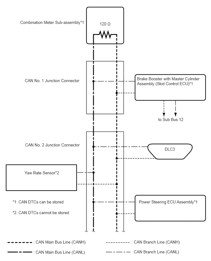

C264998E05
3.385,0.729 4.083,0.958 0.698,0.229 10 false 120 Ω 5.594,4.99 6.167,5.323 0.573,0.333 10 false DLC3 4.656,2.594 6.927,3.135 2.271,0.542 10 false Brake Booster with Master Cylinder Assembly (Skid Control ECU)*1 4.719,6.781 6.896,7.167 2.177,0.385 10 false Power Steering ECU Assembly*1 1.135,8.146 3.094,8.469 1.958,0.323 10 false : CAN Main Bus Line (CANH) 4.469,8.146 6.177,8.469 1.708,0.323 10 false : CAN Branch Line (CANH) 4.469,8.479 6.156,8.802 1.688,0.323 10 false : CAN Branch Line (CANL) 1.135,8.49 3.094,8.813 1.958,0.323 10 false : CAN Main Bus Line (CANL) 0.844,2.656 2.813,2.958 1.969,0.302 10 false CAN No. 1 Junction Connector 0.688,0.677 3.063,0.833 2.375,0.156 10 false Combination Meter Sub-assembly*1 5.375,3.979 6.333,4.25 0.958,0.271 10 false to Sub Bus 12 0.833,5.792 2.156,6.042 1.323,0.25 10 false Yaw Rate Sensor*2 0.854,4.844 2.823,5.146 1.969,0.302 10 false CAN No. 2 Junction Connector 0.427,6.781 2.24,7.083 1.813,0.302 10 false *1: CAN DTCs can be stored 0.427,7.146 2.438,7.542 2.01,0.396 10 false *2: CAN DTCs cannot be stored

C264999E05
0.646,2.885 2.333,3.115 1.688,0.229 10 false Airbag ECU Assembly*4 3.396,7.156 4.094,7.385 0.698,0.229 10 false 120 Ω 4.625,2.271 6.885,2.646 2.26,0.375 10 false Spiral Cable with Sensor Sub-assembly (Steering Angle Sensor)*4 4.271,7.74 4.74,8.031 0.469,0.292 10 false ECM*3 4.656,0.469 6.906,0.938 2.25,0.469 10 false Navigation Receiver Assembly*1*3 1.271,8.156 3.229,8.479 1.958,0.323 10 false : CAN Main Bus Line (CANH) 4.5,8.167 6.208,8.49 1.708,0.323 10 false : CAN Branch Line (CANH) 4.5,8.49 6.188,8.813 1.688,0.323 10 false : CAN Branch Line (CANL) 1.271,8.469 3.229,8.792 1.958,0.323 10 false : CAN Main Bus Line (CANL) 0.813,0.469 2.781,0.771 1.969,0.302 10 false CAN No. 2 Junction Connector 0.49,1.281 2.375,1.854 1.885,0.573 10 false Certification ECU (Smart Key ECU Assembly)*3 0.74,4.063 2.708,4.365 1.969,0.302 10 false CAN No. 3 Junction Connector 0.292,4.573 1.74,5 1.448,0.427 10 false Power Management Control ECU*3*5 0.333,5.948 1.313,6.25 0.979,0.302 10 false to Sub Bus 11 1.604,5.958 2.563,6.26 0.958,0.302 10 false to Sub Bus 12 4.76,4.073 6.917,4.74 2.156,0.667 10 false Transmission Control ECU Assembly*3 4.656,1.104 6.531,1.531 1.875,0.427 10 false Radio and Display Receiver Assembly*2*3 0.354,6.344 2.552,6.635 2.198,0.292 10 false *1: for Navigation Receiver Type 0.354,6.677 2.552,6.969 2.198,0.292 10 false *2: for Radio and Display Type 0.354,7.01 2.552,7.302 2.198,0.292 10 false *3: CAN DTCs can be stored 0.354,7.344 2.552,7.635 2.198,0.292 10 false *4: CAN DTCs cannot be stored 0.354,7.677 2.719,7.969 2.365,0.292 10 false *5: Gateway function equipped ECU 4.896,5.417 6.583,5.865 1.688,0.448 10 false Main Body ECU (Multiplex Network Body ECU)*3 4.833,6.667 6.875,6.906 2.042,0.24 10 false to LIN Communication System 4.833,7.26 5.958,7.563 1.125,0.302 10 false to Sub Bus 12


HINT:

The CAN communication system connects to other networks via ECUs that function as a gateway (See page Power Source / Network>NETWORKING>LIN COMMUNICATION SYSTEM>SYSTEM DIAGRAM).


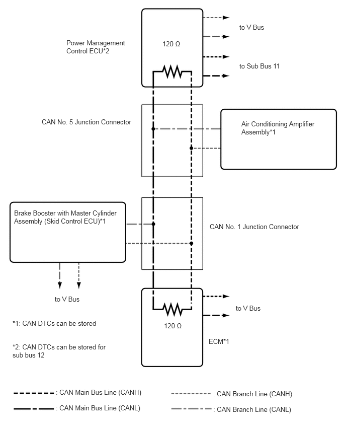
SUB BUS 11
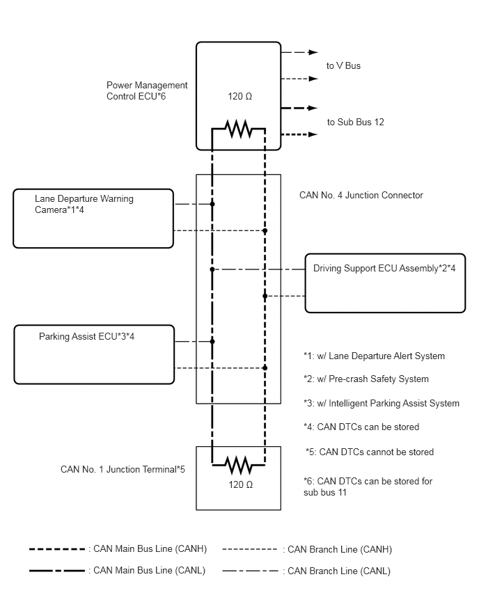

C316697E02
0.583,4.948 2.521,5.385 1.938,0.438 10 false Parking Assist ECU*3*4 3.417,7.167 4.115,7.396 0.698,0.229 10 false 120 Ω 1.323,8.125 3.281,8.448 1.958,0.323 10 false : CAN Main Bus Line (CANH) 4.229,8.135 5.927,8.458 1.698,0.323 10 false : CAN Branch Line (CANH) 4.229,8.458 5.927,8.781 1.698,0.323 10 false : CAN Branch Line (CANL) 1.323,8.448 3.281,8.771 1.958,0.323 10 false : CAN Main Bus Line (CANL) 1.594,1.188 2.906,1.594 1.313,0.406 10 false Power Management Control ECU*6 0.521,2.885 2.229,3.229 1.708,0.344 10 false Lane Departure Warning Camera*1*4 4.479,2.833 6.448,3.135 1.969,0.302 10 false CAN No. 4 Junction Connector 4.542,5.24 6.958,5.531 2.417,0.292 10 false *1: w/ Lane Departure Alert System 4.542,5.583 6.969,5.781 2.427,0.198 10 false *2: w/ Pre-crash Safety System 3.406,1.354 4.104,1.583 0.698,0.229 10 false 120 Ω 4.542,5.948 7.146,6.292 2.604,0.344 10 false *3: w/ Intelligent Parking Assist System 4.688,3.927 6.99,4.24 2.302,0.313 10 false Driving Support ECU Assembly*2*4 4.896,1.74 6.677,1.948 1.781,0.208 10 false to Sub Bus 12 4.885,0.896 5.594,1.146 0.708,0.25 10 false to V Bus 4.542,6.302 6.844,6.646 2.302,0.344 10 false *4: CAN DTCs can be stored 4.542,7.115 6.583,7.75 2.042,0.635 10 false *6: CAN DTCs can be stored for sub bus 11 0.906,6.938 3.083,7.375 2.177,0.438 10 false CAN No. 1 Junction Terminal*5 4.573,6.677 6.875,7.021 2.302,0.344 10 false *5: CAN DTCs cannot be stored


SUB BUS 12


C265001E04
3.396,6.656 3.896,6.885 0.5,0.229 10 false 120 Ω 4.323,6.979 4.906,7.292 0.583,0.313 10 false ECM*1 1.156,8.031 3.115,8.354 1.958,0.323 10 false : CAN Main Bus Line (CANH) 4.417,8.063 6.125,8.385 1.708,0.323 10 false : CAN Branch Line (CANH) 4.417,8.385 6.115,8.708 1.698,0.323 10 false : CAN Branch Line (CANL) 1.156,8.354 3.115,8.677 1.958,0.323 10 false : CAN Main Bus Line (CANL) 1.375,0.802 2.823,1.344 1.448,0.542 10 false Power Management Control ECU*2 5,2.479 6.781,3.063 1.781,0.583 10 false Air Conditioning Amplifier Assembly*1 0.865,2.438 2.833,2.74 1.969,0.302 10 false CAN No. 5 Junction Connector 0.292,4.323 2.531,4.771 2.24,0.448 10 false Brake Booster with Master Cylinder Assembly (Skid Control ECU)*1 4.885,6.292 5.615,6.49 0.729,0.198 10 false to V Bus 4.958,0.479 5.688,0.677 0.729,0.198 10 false to V Bus 4.958,1.281 5.906,1.479 0.948,0.198 10 false to Sub Bus 11 1.135,6.104 1.865,6.302 0.729,0.198 10 false to V Bus 3.365,0.823 3.865,1.052 0.5,0.229 10 false 120 Ω 4.344,4.604 6.271,4.906 1.927,0.302 10 false CAN No. 1 Junction Connector 0.26,6.604 2.229,6.906 1.969,0.302 10 false *1: CAN DTCs can be stored 0.26,7.094 2.292,7.573 2.031,0.479 10 false *2: CAN DTCs can be stored for sub bus 12


SUB BUS 13(w/ Pre-crash Safety System)
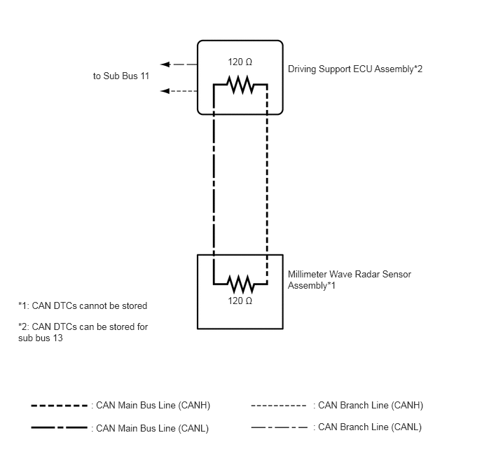

C278135E05
3.385,4.385 3.813,4.615 0.427,0.229 10 false 120 Ω 3.385,0.833 3.813,1.063 0.427,0.229 10 false 120 Ω 1.385,1.042 2.354,1.208 0.969,0.167 10 false to Sub Bus 11 1.354,5.938 3.313,6.26 1.958,0.323 10 false : CAN Main Bus Line (CANH) 4.656,5.938 6.365,6.26 1.708,0.323 10 false : CAN Branch Line (CANH) 4.656,6.26 6.344,6.583 1.688,0.323 10 false : CAN Branch Line (CANL) 1.354,6.281 3.313,6.604 1.958,0.323 10 false : CAN Main Bus Line (CANL) 4.281,0.938 6.563,1.271 2.281,0.333 10 false Driving Support ECU Assembly*2 4.281,3.99 6.271,4.594 1.99,0.604 10 false Millimeter Wave Radar Sensor Assembly*1 0.271,4.458 2.427,4.656 2.156,0.198 10 false *1: CAN DTCs cannot be stored 0.271,4.771 2.385,5.198 2.115,0.427 10 false *2: CAN DTCs can be stored for sub bus 13