RM2070E
_58
Vehicle Interior
_061938
THEFT DETERRENT / KEYLESS ENTRY
_0301768
ENTRY AND START SYSTEM(for Start Function)
U
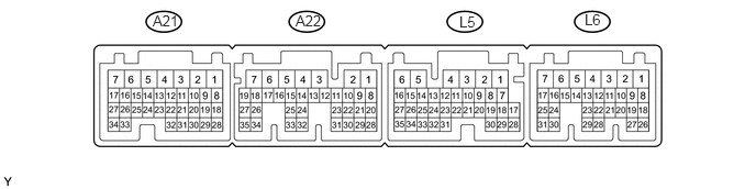
THEFT DETERRENT / KEYLESS ENTRY ENTRY AND START SYSTEM(for Start Function) TERMINALS OF ECU
CHECK POWER MANAGEMENT CONTROL ECU
2.802,0.115 3.063,0.354
0.26,0.24
10
false
A22
4.354,0.125 4.625,0.302
0.271,0.177
10
false
L5
1.448,0.115 1.708,0.302
0.26,0.188
10
false
A21
5.542,0.104 5.802,0.365
0.26,0.26
10
false
L6
a.
Disconnect the A22, L5 and L6 connectors.
b.
Measure the voltage and resistance according to the value(s) in the table below.
| Tester Connection | Input/Output | Wiring Color | Terminal Description | Condition | Specified Condition | Related Data List Item |
|---|---|---|---|---|---|---|
| A22-2 (IG2D) - Body ground | Output | V - Body ground | IG2 signal | 20°C (68°F) | 130 to 230 Ω | IG2 Relay Monitor (Outside) |
| A22-23 (STP) - Body ground | Input | L - Body ground | Stop light switch signal | Brake pedal depressed → Brake pedal released | 9 V or higher → 1 V or less | Stop Light Switch1 |
| L5-1 (AM22) - Body ground | Input | W - Body ground | +B power supply | Power switch off | 9.5 to 16 V | - |
| L6-7 (AM21) - Body ground | Input | Y - Body ground | +B power supply | Power switch off | 9.5 to 16 V | - |
| L5-6 (E1) - Body ground | - | W-B - Body ground | Ground | Always | Below 1 Ω | - |
| L6-4 (E12) - Body ground | - | W-B - Body ground | Ground | Always | Below 1 Ω | - |
| L6-24 (CA1L) - Body ground | Input/Output | P - Body ground | CAN communication line | Always | 10 kΩ or higher | - |
| L6-25 (CA1H) - Body ground | Input/Output | V - Body ground | CAN communication line | Always | 10 kΩ or higher | - |
| L6-17 (SSW2) - Body ground | Input | Y - Body ground | SSW2 contact signal (backup for SSW1 and has same behavior as SSW1)
|
Power switch pushed → Power switch not pushed | Below 1 Ω → 10 kΩ or higher | Start Switch2 |
| L5-7 (SSW1) - Body ground | Input | B - Body ground | SSW1 contact signal | Power switch pushed → Power switch not pushed | Below 1 Ω → 10 kΩ or higher | Start Switch1 |
| L6-1 (ACCD) - Body ground | Output | G - Body ground | ACC signal | 20°C (68°F) | 81.49 to 118.98 Ω | ACC Relay Monitor |
| L6-2 (IG1D) - Body ground | Output | B - Body ground | IG1 signal | 20°C (68°F) | 54.32 to 79.32 Ω | IG1 Relay Monitor (Outside) |
| L6-11 (LIN2) - Body ground | Input/Output | L - Body ground | LIN communication line | Always | 10 kΩ or higher | - |
If the result is not as specified, there may be a malfunction in the wire harness.
c.
Reconnect the A22, L5 and L6 connectors.
d.
Measure the voltage and check for pulses according to the value(s) in the table below.
| Tester Connection | Input/Output | Wiring Color | Terminal Description | Condition | Specified Condition | Related Data List Item |
|---|---|---|---|---|---|---|
| A22-2 (IG2D) - L5-6 (E1) | Output | V - W-B | IG2 signal | Power switch on (ACC) → Power switch on (IG) | 1 V or less → 9 V or higher | IG2 Relay Monitor (Outside) |
| L5-9 (INDW) - L5-6 (E1) | Output | BE - W-B | Power switch indicator (orange) illumination output | Brake pedal released, park (P) selected, power switch on (ACC), or on (IG) → Other than previous condition | 7 V or higher → 1 V or less | - |
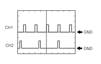
| A22-22 (PCON) - L5-6 (E1) | Output | LG - W-B | P position signal | Park (P) selected | Pulse generation
(See waveform 1) |
- |
| A22-28 (PPOS) - L5-6 (E1) | Input | W - W-B | P position signal | Park (P) selected | Pulse generation
(See waveform 1) |
- |
| L6-17 (SSW2) - L5-6 (E1) | Output | Y - W-B | SSW2 contact signal (backup for SSW1 and has same behavior as SSW1)
|
Power switch pushed → Power switch not pushed | 9 V or higher → 1 V or less | Start Switch2 |
| L5-7 (SSW1) - L5-6 (E1) | Output | B - W-B | Power switch signal | Power switch pushed → Power switch not pushed | 9 V or higher → 1 V or less | Start Switch1 |
| L6-1 (ACCD) - L5-6 (E1) | Output | G - W-B | ACC signal | Power switch off → Power switch on (ACC) | 1 V or less → 9 V or higher | ACC Relay Monitor |
| L6-2 (IG1D) - L5-6 (E1) | Output | B - W-B | IG1 signal | Power switch on (ACC) → Power switch on (IG) | 1 V or less → 9 V or higher | IG1 Relay Monitor (Outside) |
| L5-8 (INDS) - L5-6 (E1) | Output | R - W-B | Power switch indicator (green) illumination output | Brake pedal depressed, park (P) selected | 7 V or higher | - |
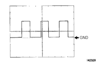
| L5-14 (SPDI) - L5-6 (E1) | Input | V - W-B | Vehicle speed signal | Power switch on (IG), vehicle being driven at approx. 5 km/h (3 mph) | Pulse generation
(See waveform 2) |
Vehicle Speed Signal |
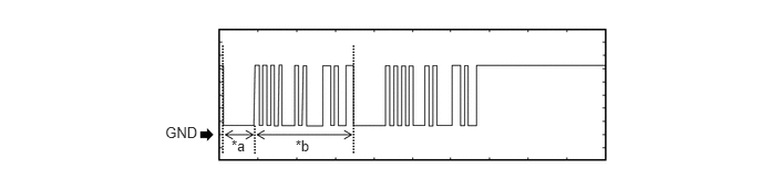
| L6-20 (IMO) - L5-6 (E1) | Output | SB - W-B | ID code box communication input
(Signal input from power management control ECU to ID code box) |
Power switch off | 11 to 14 V | ·
Engine Start Request ·
EFI Code Receive |
| Within 3 seconds of hybrid control system start or within 3 seconds of power switch turned on (IG) after auxiliary battery cable disconnected and reconnected | Pulse generation
(See waveform 3) |
|||||
| L6-21 (IMI) - L5-6 (E1) | Input | LG - W-B | ID code box communication output
(Signal output from ID code box to power management control ECU) |
Power switch off | 11 to 14 V | |
| Power switch on (IG) | Pulse generation
(See waveform 3) |
e.
Using an oscilloscope, check the signal waveform of the ECU.
i.
0.167,0.854 0.552,1.083
0.385,0.229
10
false
CH1
0.188,1.469 0.573,1.698
0.385,0.229
10
false
CH2
2.844,1.01 3.229,1.24
0.385,0.229
10
false
GND
2.844,1.573 3.229,1.802
0.385,0.229
10
false
GND
Waveform 1
| Tester Connection | CH1: A22-22 (PCON) - L5-6 (E1)
CH2: A22-28 (PPOS) - L5-6 (E1) |
| Tool Setting | 10 V/DIV., 10 ms./DIV. |
| Vehicle Condition | Park (P) selected |
ii.
2.823,1.24 3.167,1.438
0.344,0.198
10
false
GND
Waveform 2
| Tester Connection | L5-14 (SPDI) - L5-6 (E1) |
| Tool Setting | 5 V/DIV., 10 ms./DIV. |
| Vehicle Condition | Power switch on (IG), vehicle being driven at approx. 5 km/h (3 mph) |
- HINT:
-
The wavelength becomes shorter as the vehicle speed increases.
iii.
Waveform 1 (Reference)
2.177,1.292 2.365,1.468
0.188,0.176
10
*a
2.779,1.296 2.967,1.472
0.188,0.176
10
*b
1.554,1.171 1.884,1.346
0.331,0.176
10
GND
| *a | Approximately 160 ms | *b | Approximately 510 ms |
| Item | Content |
|---|---|
| Tester Connection | L6-20 (IMO) - L5-6 (E1) |
| Tool Setting | 2 V/DIV., 200 ms./DIV. |
| Condition | Within 3 seconds of hybrid control system start or within 3 seconds of power switch turned on (IG) after auxiliary battery cable disconnected and reconnected |
iv.
Waveform 2 (Reference)
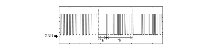
3.499,1.324 3.687,1.500
0.188,0.176
10
*a
4.102,1.328 4.290,1.504
0.188,0.176
10
*b
1.554,1.171 1.884,1.346
0.331,0.176
10
GND
| *a | Approximately 160 ms | *b | Approximately 510 ms |
| Item | Content |
|---|---|
| Tester Connection | L6-21 (IMI) - L5-6 (E1) |
| Tool Setting | 2 V/DIV., 200 ms./DIV. |
| Condition | Power switch on (IG) |