RM2070E
_58
Vehicle Interior
_061939
LIGHTING (INT)
_0301790
LIGHTING SYSTEM
J
LIGHTING (INT) LIGHTING SYSTEM Interior Light Power Source Circuit
DESCRIPTION
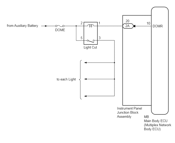
The main body ECU (multiplex network body ECU) controls operation of the light cut relay in order to supply power to the interior lights.
WIRING DIAGRAM
0.281,0.958 2,1.479
1.719,0.521
10
false
from Auxiliary Battery
2.26,1.135 2.833,1.51
0.573,0.375
10
false
DOME
3.302,0.854 3.875,1.229
0.573,0.375
10
false
2
4.031,0.854 4.604,1.229
0.573,0.375
10
false
1
4.042,1.458 4.615,1.833
0.573,0.375
10
false
3
3.302,1.458 3.875,1.833
0.573,0.375
10
false
5
3.427,1.844 4.219,2.26
0.792,0.417
10
false
Light Cut
2.323,3.146 3.99,3.646
1.667,0.5
10
false
to each Light
4.792,4.333 5.875,5.01
1.083,0.677
10
false
Instrument Panel Junction Block Assembly
5.896,4.677 6.469,5.052
0.573,0.375
10
false
MB
5.896,4.844 7.083,5.5
1.188,0.656
10
false
Main Body ECU (Multiplex Network Body ECU)
5.135,0.969 5.708,1.344
0.573,0.375
10
false
2A
5.146,0.771 5.719,1.146
0.573,0.375
10
false
20
6,0.865 6.573,1.24
0.573,0.375
10
false
10
6.25,0.979 6.823,1.354
0.573,0.375
10
false
DOMR
CAUTION / NOTICE / HINT
- NOTICE:
-
Inspect the fuses for circuits related to this system before performing the following inspection procedure.
PROCEDURE
1.INSPECT LIGHT CUT RELAY
a.
Remove the light cut relay.
b.
Inspect the light cut relay (See page Vehicle Interior>LIGHTING (INT)>RELAY>ON-VEHICLE INSPECTION)
OK
2.CHECK HARNESS AND CONNECTOR (AUXILIARY BATTERY - LIGHT CUT RELAY)
NG
REPLACE LIGHT CUT RELAY
2.CHECK HARNESS AND CONNECTOR (AUXILIARY BATTERY - LIGHT CUT RELAY)
a.
Measure the voltage according to the value(s) in the table below.
- Standard Voltage:
Tester Connection Condition Specified Condition Relay Terminal 5 - Body ground Power switch off 11 to 14 V
OK
REPAIR OR REPLACE HARNESS OR CONNECTOR (LIGHT CUT RELAY - EACH LIGHT)
NG
REPAIR OR REPLACE HARNESS OR CONNECTOR