INTERIOR PANELS / TRIM ROOF SUNSHADE SYSTEM B2341 Sensor (Motor) Failure B2344 Position Failure
DESCRIPTION
When the roof sunshade ECU (sliding roof drive gear assembly) detects a motor malfunction and the roof sunshade operation is stopped, DTC B2341 is output.
When the roof sunshade ECU (sliding roof drive gear assembly) detects a gear position malfunction and the roof sunshade operation is stopped, DTC B2344 is output.
| DTC Code | DTC Detection Condition | Trouble Area |
|---|---|---|
| B2341 | Sensor (motor) failure (When the ECU enters fail-safe mode due to a problem with the motor) | ·
Roof sunshade ECU (Sliding roof drive gear assembly) ·
Roof sunshade switch (Map light assembly) ·
Wire harness or connector |
| B2344 | Position failure (When the ECU enters fail-safe mode due to a problem with the gear position) | ·
Roof sunshade ECU (Sliding roof drive gear assembly) ·
Roof sunshade switch (Map light assembly) ·
Wire harness or connector |
WIRING DIAGRAM
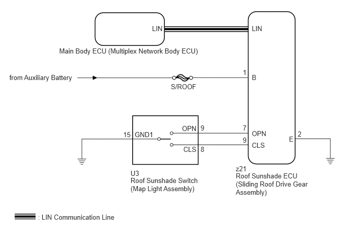
CAUTION / NOTICE / HINT
- NOTICE:
- ·
Inspect the fuses for circuits related to this system before performing the following inspection procedure.
·When the roof sunshade ECU (sliding roof drive gear assembly) is replaced or removed and reinstalled, it requires initialization (See page Vehicle Interior>INTERIOR PANELS / TRIM>ROOF SUNSHADE SYSTEM>INITIALIZATION).
PROCEDURE
Check the roof sunshade auto operation (See page Vehicle Interior>INTERIOR PANELS / TRIM>ROOF SUNSHADE SYSTEM>OPERATION CHECK).
- OK:
Auto operation operates normally.
OK
NG
Clear the DTCs (See page Vehicle Interior>INTERIOR PANELS / TRIM>ROOF SUNSHADE SYSTEM>DTC CHECK / CLEAR).
Recheck for DTCs.
- OK:
DTC B2341 or B2344 is not output.
OK
(See pageGeneral>INTRODUCTION>HOW TO TROUBLESHOOT ECU CONTROLLED SYSTEMS>HOW TO PROCEED WITH TROUBLESHOOTING)
NG
Check that the roof sunshade ECU (sliding roof drive gear assembly) can be initialized (See page Vehicle Interior>INTERIOR PANELS / TRIM>ROOF SUNSHADE SYSTEM>INITIALIZATION).
- OK:
Roof sunshade ECU (sliding roof drive gear assembly) can be initialized.
OK
NG
Clear the DTCs (See page Vehicle Interior>INTERIOR PANELS / TRIM>ROOF SUNSHADE SYSTEM>DTC CHECK / CLEAR).
Recheck for DTCs.
- OK:
DTC B2341 or B2344 is not output.
OK
NG
Disconnect the U3 roof sunshade switch (map light assembly) connector.
Disconnect the z21 roof sunshade ECU (sliding roof drive gear assembly) connector.
Measure the resistance according to the value(s) in the table below.
- Standard Resistance:
Tester Connection Condition Specified Condition z21-9 (CLS) - U3-8 (CLS) Always Below 1 Ω z21-9 (CLS) - Body ground Always 10 kΩ or higher z21-7 (OPN) - U3-9 (OPN) Always Below 1 Ω z21-7 (OPN) - Body ground Always 10 kΩ or higher U3-15 (GND1) - Body ground Always Below 1 Ω z21-2 (E) - Body ground Always Below 1 Ω
OK
NG
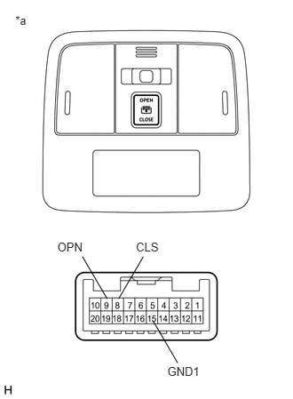
Remove the roof sunshade switch (map light assembly) (See page Vehicle Interior>INTERIOR PANELS / TRIM>ROOF SUNSHADE SWITCH>REMOVAL).
Measure the resistance according to the value(s) in the table below.
- Standard Resistance:
Tester Connection Condition Specified Condition 8 (CLS) - 15 (GND1) CLOSE switch is pressed Below 1 Ω 8 (CLS) - 15 (GND1) CLOSE switch is not pressed 10 kΩ or higher 9 (OPN) - 15 (GND1) OPEN switch is pressed Below 1 Ω 9 (OPN) - 15 (GND1) OPEN switch is not pressed 10 kΩ or higher
| *a | Component without harness connected
(Roof Sunshade Switch (Map Light Assembly)) |
OK
NG