RM2070E
_59
Vehicle Exterior
_061953
LIGHTING (EXT)
_0301912
REAR COMBINATION LIGHT ASSEMBLY
G
LIGHTING (EXT) REAR COMBINATION LIGHT ASSEMBLY ON-VEHICLE INSPECTION
PROCEDURE

 81560
1.INSPECT REAR COMBINATION LIGHT ASSEMBLY LH
a.
1.579,1.198 1.850,1.379
0.272,0.181
10
R17
0.131,0.103 0.341,0.287
0.210,0.184
10
*a
1.789,2.909 1.926,3.069
0.137,0.160
10
E
2.643,1.983 2.804,2.145
0.162,0.162
10
B
2.581,2.071 2.18,2.071
false
0.735,1.983 0.896,2.145
0.162,0.162
10
B
1.292,2.071 0.891,2.071
false
1.849,2.449 1.849,2.878
false
2.056,2.909 2.198,3.069
0.142,0.160
10
B
2.111,2.449 2.111,2.878
false
1.536,2.909 1.678,3.062
0.142,0.153
10
B
1.596,2.449 1.596,2.878
false
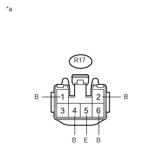
Disconnect the connector from the rear combination light assembly LH.
b.
Measure the voltage according to the value(s) in the table below.
- Standard Voltage:
Tester Connection Condition Specified Condition R17-1 (B)*1 - R17-5 (E) Light control switch in tail position and rear fog light switch off Below 1 V Light control switch in tail position and rear fog light switch on 11 to 14 V R17-2 (B) - R17-5 (E) Light control switch off Below 1 V Light control switch in tail position 11 to 14 V R17-4 (B) - R17-5 (E) Brake pedal released Below 1 V Brake pedal depressed 11 to 14 V R17-6 (B) - R17-5 (E) Turn signal switch in neutral position Below 1 V Power switch on (IG) and turn signal switch in left turn position 11 to 14 V (60 to 120 times per minute)
*1: for LHD
| *a | Front view of wire harness connector
(to Rear Combination Light Assembly LH) |
If the result is not as specified, repair or replace the wire harness or connector.
81550
2.INSPECT REAR COMBINATION LIGHT ASSEMBLY RH
a.
1.579,1.194 1.850,1.376
0.272,0.181
10
S18
0.131,0.099 0.341,0.284
0.210,0.184
10
*a
1.798,2.881 1.935,3.040
0.137,0.159
10
E
2.663,1.972 2.816,2.129
0.153,0.157
10
B
2.602,2.06 2.201,2.06
false
0.738,1.972 0.891,2.129
0.153,0.157
10
B
1.296,2.06 0.894,2.06
false
1.858,2.42 1.858,2.85
false
1.536,2.881 1.673,3.044
0.137,0.163
10
B
1.596,2.42 1.596,2.85
false
2.051,2.881 2.185,3.044
0.134,0.163
10
B
2.111,2.42 2.111,2.85
false
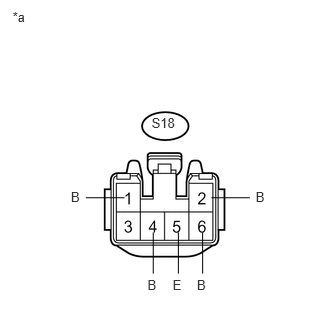
Disconnect the connector from the rear combination light assembly RH.
b.
Measure the voltage according to the value(s) in the table below.
- Standard Voltage:
Tester Connection Condition Specified Condition S18-1 (B)*1 - S18-5 (E) Light control switch in tail position and rear fog light switch off Below 1 V Light control switch in tail position and rear fog light switch on 11 to 14 V S18-2 (B) - S18-5 (E) Light control switch off Below 1 V Light control switch in tail position 11 to 14 V S18-4 (B) - S18-5 (E) Brake pedal released Below 1 V Brake pedal depressed 11 to 14 V S18-6 (B) - S18-5 (E) Turn signal switch in neutral position Below 1 V Power switch on (IG) and turn signal switch in right turn position 11 to 14 V (60 to 120 times per minute)
*1: for RHD
| *a | Front view of wire harness connector
(to Rear Combination Light Assembly RH) |
If the result is not as specified, repair or replace the wire harness or connector.