RM2070E
_59
Vehicle Exterior
_061953
LIGHTING (EXT)
_0301916
HAZARD WARNING SWITCH
G
LIGHTING (EXT) HAZARD WARNING SWITCH INSPECTION
PROCEDURE

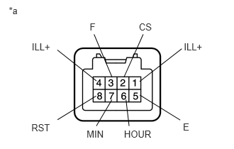
 1.INSPECT HAZARD WARNING SIGNAL SWITCH ASSEMBLY
0.13,0.071 0.323,0.245
0.193,0.174
10
*a
2.688,1.777 2.835,1.952
0.147,0.174
10
E
1.318,0.317 1.437,0.475
0.119,0.158
10
F
1.647,1.136 1.381,0.503
false
0.467,0.609 0.787,0.767
0.320,0.158
10
ILL+
2.701,0.609 3.022,0.767
0.320,0.158
10
ILL+
1.416,1.187 0.842,0.733
false
2.04,0.317 2.274,0.475
0.235,0.158
10
CS
1.819,1.136 2.103,0.503
false
1.822,1.881 2.269,2.039
0.448,0.158
10
HOUR
1.85,1.462 1.896,1.849
false
2.054,1.395 2.647,1.762
false
1.272,1.881 1.581,2.039
0.309,0.158
10
MIN
1.644,1.462 1.415,1.849
false
0.461,1.789 0.791,1.947
0.330,0.158
10
RST
1.412,1.408 0.844,1.757
false
2.051,1.196 2.67,0.715
false
a.
Hazard Warning Switch Inspection
i.
Measure the resistance according to the value(s) in the table below.
- Standard Resistance:
Tester Connection Condition Specified Condition 3 (F) - 5 (E) Hazard warning switch not pressed 10 kΩ or higher Hazard warning switch pressed Below 1 Ω
b.
Rheostat Switch (Pattern Select Switch) Inspection
i.
Measure the resistance according to the value(s) in the table below.
- Standard Resistance:
Tester Connection Condition Specified Condition 2 (CS) - 5 (E) Rheostat switch (pattern select switch) not pressed 10 kΩ or higher Rheostat switch (pattern select switch) pressed Below 1 Ω
c.
Time Adjust Switch Inspection
i.
Measure the resistance according to the value(s) in the table below.
- Standard Resistance:
Tester Connection Condition Specified Condition 6 (HOUR) - 5 (E) Hour adjust switch not pressed 10 kΩ or higher Hour adjust switch pressed Below 1 Ω 7 (MIN) - 5 (E) Minute adjust switch not pressed 10 kΩ or higher Minute adjust switch pressed Below 1 Ω 8 (RST) - 5 (E) Second adjust switch not pressed 10 kΩ or higher Second adjust switch pressed Below 1 Ω
d.
Illumination Inspection
i.
Apply auxiliary battery voltage to the hazard warning signal switch and check that the switch illuminates.
- OK:
Tester Connection Specified Condition Auxiliary battery positive (+) → Terminal 4 (ILL+)
Auxiliary battery negative (-) → Terminal 1 (ILL-)Illuminates
| *a | Component without harness connected
(Hazard Warning Signal Switch Assembly) |
If the result is not as specified, replace the integration control and panel sub-assembly.