RM2070E
_59
Vehicle Exterior
_061953
LIGHTING (EXT)
_0301921
STOP LIGHT CONTROL RELAY
G
LIGHTING (EXT) STOP LIGHT CONTROL RELAY INSPECTION
PROCEDURE

 895A0A
1.INSPECT STOP LIGHT CONTROL ECU ASSEMBLY
a.
0.144,0.056 0.337,0.249
0.193,0.193
10
*a
0.673,1.702 0.996,1.874
0.323,0.172
10
STP
1.255,1.702 1.468,1.874
0.214,0.172
10
+B
1.662,1.702 2.001,1.874
0.339,0.172
10
GND
1.197,1.321 0.894,1.67
false
1.409,1.326 1.409,1.679
false
1.828,1.326 1.828,1.679
false
2.674,1.041 2.938,1.222
0.264,0.181
10
A28
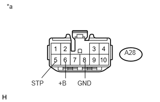
Disconnect the A28 stop light control ECU assembly connector.
b.
Measure the voltage according to the value(s) in the table below.
- Standard Voltage:
Tester Connection Condition Specified Condition A28-5 (STP) - Body ground Brake pedal released Below 1 V Brake pedal depressed 11 to 14 V A28-6 (+B) - Body ground Power switch off 11 to 14 V
| *a | Front view of wire harness connector
(to Stop Light Control ECU Assembly) |
If the result is not as specified, repair or replace the wire harness or connector.
c.
Measure the resistance according to the value(s) in the table below.
- Standard Resistance:
Tester Connection Condition Specified Condition A28-8 (GND) - Body ground Always Below 1 Ω
If the result is not as specified, repair or replace the wire harness or connector.
d.
2.24,1.635 2.667,1.052
true
0.198,0.115 0.385,0.302
0.188,0.188
10
false
*a
2.76,0.885 3.094,1.052
0.333,0.167
10
false
OUT
2.813,1.688 3.073,1.865
0.26,0.177
10
false
A28
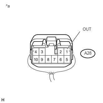
Reconnect the A28 stop light control ECU assembly connector.
e.
Measure the voltage according to the value(s) in the table below.
- Standard Voltage:
Tester Connection Condition Specified Condition A28-1 (OUT) - Body ground Brake pedal released Below 1 V Brake pedal depressed 11 to 14 V
| *a | Component without harness connected
(Stop Light Control ECU Assembly) |
If the result is not as specified, the stop light control ECU assembly may have a malfunction.