EXTERIOR PANELS / TRIM FRONT DOOR BELT MOULDING REMOVAL
PROCEDURE

 1. PRECAUTION
- NOTICE:
-
After turning the power switch off, waiting time may be required before disconnecting the cable from the negative (-) auxiliary battery terminal. Therefore, make sure to read the disconnecting the cable from the negative (-) auxiliary battery terminal notices before proceeding with work (See page General>INTRODUCTION>REPAIR INSTRUCTION>PRECAUTION).
58410B
2.REMOVE DECK BOARD ASSEMBLY
58411A
3.REMOVE NO. 1 DECK BOARD
58412A
4.REMOVE NO. 2 DECK BOARD
64993
5.REMOVE REAR DECK FLOOR BOX
64995
6.REMOVE DECK FLOOR BOX RH
7.DISCONNECT CABLE FROM NEGATIVE AUXILIARY BATTERY TERMINAL
- NOTICE:
-
When disconnecting the cable, some systems need to be initialized after the cable is reconnected (See page General>INTRODUCTION>REPAIR INSTRUCTION>INITIALIZATION).
69284C
8.REMOVE FRONT DOOR INSIDE HANDLE BEZEL PLUG
9.REMOVE MULTIPLEX NETWORK MASTER SWITCH ASSEMBLY WITH FRONT DOOR ARMREST BASE PANEL (for Driver Side)
10.REMOVE POWER WINDOW REGULATOR SWITCH ASSEMBLY WITH FRONT DOOR ARMREST BASE PANEL (for Front Passenger Side)
74222
11.REMOVE DOOR ARMREST COVER
67602
12.REMOVE FRONT DOOR TRIM BOARD SUB-ASSEMBLY
67626
13.REMOVE FRONT DOOR TRIM BRACKET
67832
14.REMOVE FRONT DOOR SERVICE HOLE COVER
68102
15.REMOVE FRONT DOOR GLASS SUB-ASSEMBLY
68151D
16.REMOVE FRONT DOOR GLASS RUN
75720
17.REMOVE FRONT DOOR BELT MOULDING ASSEMBLY
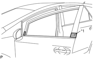
Put protective tape around the front door belt moulding assembly.
| *1 | Protective Tape |
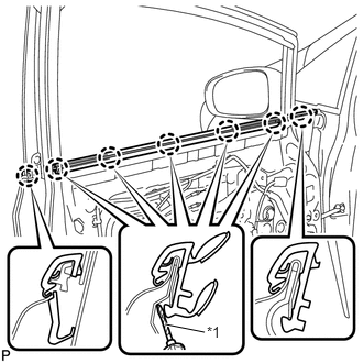
Using a screwdriver, disengage the 7 claws and remove the front door belt moulding assembly.
| *1 | Protective Tape |
- HINT:
-
Tape the screwdriver tip before use.