METER / GAUGE / DISPLAY METER / GAUGE SYSTEM Malfunction in Water Temperature Warning Light
DESCRIPTION
In this circuit, the combination meter sub-assembly receives engine coolant temperature signals from the ECM using the CAN communication system. The combination meter sub-assembly displays engine coolant temperature warnings based on the data received from the ECM.
WIRING DIAGRAM
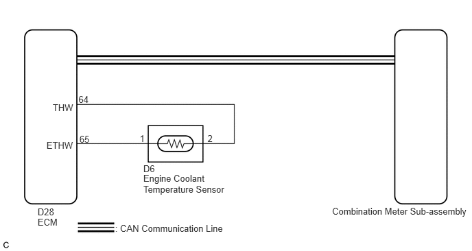
CAUTION / NOTICE / HINT
- HINT:
- ·
If there is an open or short in the engine coolant temperature sensor circuit, the ECM stores the DTCs. Troubleshoot the SFI system (See page Engine / Hybrid System>2ZR-FXE (ENGINE CONTROL)>SFI SYSTEM>HOW TO PROCEED WITH TROUBLESHOOTING).
·If the exhaust heat recirculation system has a malfunction, the water temperature warning light comes on to inform the driver of the malfunction.
PROCEDURE
Check if CAN communication DTCs are output (See page Power Source / Network>NETWORKING>CAN COMMUNICATION SYSTEM (w/ Central Gateway ECU)>DIAGNOSIS SYSTEM).
- Result:
Result Proceed to CAN communication DTCs are not output A CAN communication DTCs are output B
A
B
Check the Water temperature warning light.
- Result:
Result Proceed to Water temperature warning light does not come on A Water temperature warning light remains on B
A
B
Connect the GTS to the DLC3.
Turn the power switch on (IG).
Turn the GTS on.
Enter the following menus: Body Electrical / Combination Meter / Active Test.
Check the operation by referring to the table below.
| Tester Display | Test Part | Control Range | Diagnostic Note |
|---|---|---|---|
| Indicat. Lamp Coolant Hot | Engine coolant temperature warning light | OFF or ON | - |
- OK:
Water temperature warning light operation is normal.
OK
NG
Check if SFI system outputs DTCs (See page Engine / Hybrid System>2ZR-FXE (ENGINE CONTROL)>SFI SYSTEM>DTC CHECK / CLEAR ).
- Result:
Result Proceed to DTCs are not output A DTCs are output B
A
B
(See pageEngine / Hybrid System>2ZR-FXE (ENGINE CONTROL)>SFI SYSTEM>HOW TO PROCEED WITH TROUBLESHOOTING)
Connect the GTS to the DLC3.
Turn the power switch on (IG).
Turn the GTS on.
Enter the following menus:
for Combination Meter: Body Electrical / Combination Meter / Data List.
for Engine: Powertrain / Engine and ECT / Data List.
Check the values by referring to the table below.
| Tester Display | Measurement Item/Range | Normal Condition | Diagnostic Note |
|---|---|---|---|
| Coolant Temperature | Engine coolant temperature / 0 to 127.5°C (0 to 261.5°F) | After warming up: 75 to 100°C (167 to 212°F) | - |
| Tester Display | Measurement Item/Range | Normal Condition | Stored as Freeze Frame Data |
|---|---|---|---|
| Coolant Temp | Engine coolant temperature/
Min.: -40°C (-40°F), Max.: 140°C (284°F) |
75 to 100°C (167 to 212°F): After warming up | Yes |
| Diagnostic Note:
This is the engine coolant temperature.
|
|||
- NOTICE:
-
Enter inspection mode (See page General>INTRODUCTION>REPAIR INSTRUCTION>INSPECTION MODE PROCEDURE).
- HINT:
-
When the Data List values of the ECUs do not match, a signal output error of the ECM is suspected.
- Result:
Result Proceed to The data list values of the ECUs do not match A The data list values of the ECUs match B
A
B
(See pageEngine / Hybrid System>2ZR-FXE (ENGINE CONTROL)>SFI SYSTEM>HOW TO PROCEED WITH TROUBLESHOOTING)
Replace the combination meter sub-assembly with a new one (See page Vehicle Interior>METER / GAUGE / DISPLAY>COMBINATION METER>REMOVAL).
- OK:
The operation of the water temperature warning light returns to normal.
OK
NG