Home › Vehicle Exterior › LIGHTING (EXT) › LIGHTING SYSTEM › from 2020.08
RM2070E _59 Vehicle Exterior _061953 LIGHTING (EXT) _0301908 LIGHTING SYSTEM J

LIGHTING (EXT)  LIGHTING SYSTEM  Indicator Circuit  


DESCRIPTION

The headlight beam level control system indicator light in the combination meter sub-assembly comes on for approximately 3 seconds when the power switch is turned on (IG). The indicator light also comes on when the headlight leveling ECU assembly detects a malfunction.

WIRING DIAGRAM
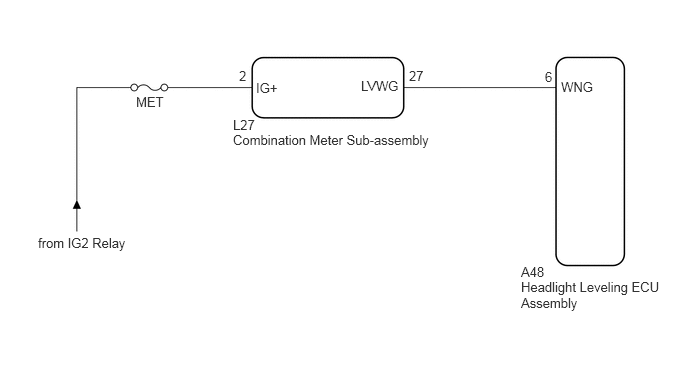
E224353E04
0.396,2.448 1.5,2.604 1.104,0.156 10 false from IG2 Relay 1.417,0.979 1.792,1.146 0.375,0.167 10 false MET 2.667,0.833 2.927,0.979 0.26,0.146 10 false IG+ 3.76,0.813 4.188,0.958 0.427,0.146 10 false LVWG 5.844,0.823 6.208,0.969 0.365,0.146 10 false WNG 2.49,0.708 2.615,0.854 0.125,0.146 10 false 2 4.26,0.708 4.479,0.854 0.219,0.146 10 false 27 5.677,0.719 5.885,0.917 0.208,0.198 10 false 6 2.427,1.375 4.719,1.521 2.292,0.146 10 false Combination Meter Sub-assembly 5.427,2.75 5.698,2.896 0.271,0.146 10 false A48 2.427,1.219 2.802,1.365 0.375,0.146 10 false L27 5.427,2.906 6.979,3.281 1.552,0.375 10 false Headlight Leveling ECU Assembly

CAUTION / NOTICE / HINT

NOTICE:

Inspect the fuses for circuits related to this system before performing the following inspection procedure.


PROCEDURE

1.CHECK HARNESS AND CONNECTOR (AUXILIARY BATTERY - COMBINATION METER SUB-ASSEMBLY)
a.

Disconnect the L27 combination meter sub-assembly connector.


b.

Measure the voltage according to the value(s) in the table below.

Standard Voltage:
Tester Connection Condition Specified Condition
L27-2 (IG+) - Body ground Power switch on (IG) 11 to 14 V
Power switch off Below 1 V


OK

2.CHECK HARNESS AND CONNECTOR (COMBINATION METER SUB-ASSEMBLY - HEADLIGHT LEVELING ECU ASSEMBLY)

NG

REPAIR OR REPLACE HARNESS OR CONNECTOR

2.CHECK HARNESS AND CONNECTOR (COMBINATION METER SUB-ASSEMBLY - HEADLIGHT LEVELING ECU ASSEMBLY)
a.

Disconnect the A48 headlight leveling ECU assembly connector.


b.

Measure the resistance according to the value(s) in the table below.

Standard Resistance:
Tester Connection Condition Specified Condition
A48-6 (WNG) - L27-27 (LVWG) Always Below 1 Ω
A48-6 (WNG) - Body ground Always 10 kΩ or higher


OK

3.INSPECT COMBINATION METER SUB-ASSEMBLY

NG

REPAIR OR REPLACE HARNESS OR CONNECTOR

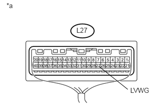
3.INSPECT COMBINATION METER SUB-ASSEMBLY
a.
U155079E04
2.042,1.365 2.646,1.844 false 1.583,0.542 1.833,0.719 0.25,0.177 10 false L27 2.698,1.781 3.125,1.958 0.427,0.177 10 false LVWG 0.135,0.031 0.292,0.208 0.156,0.177 10 false *a

Reconnect the L27 combination meter sub-assembly connector.


b.

Measure the voltage according to the value(s) in the table below.

Standard Voltage:
Tester Connection Condition Specified Condition
L27-27 (LVWG) - Body ground Power switch on (IG) 11 to 14 V


Text in Illustration
*a Component with harness connected
(Combination Meter Sub-assembly)


OK

PROCEED TO NEXT SUSPECTED AREA SHOWN IN PROBLEM SYMPTOMS TABLE

NG

REPLACE COMBINATION METER SUB-ASSEMBLY