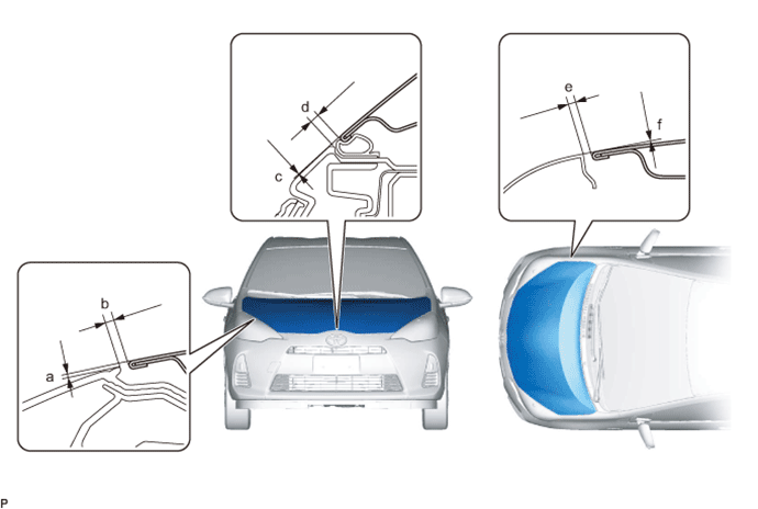
Check that the clearance measurements of areas "a" through "f" are within each standard range.
FIT STANDARD / ADJUSTMENT METHOD > ADJUSTMENT |
| INSPECT HOOD SUB-ASSEMBLY |
Check that the clearance measurements of areas "a" through "f" are within each standard range.
| Area | Measurement | Area | Measurement |
| a | -0.85 to 3.15 mm(-0.0335 to 0.124 in.) | b | 1.65 to 5.65 mm (0.0650 to 0.222 in.) |
| c | -1.85 to 2.15 mm (-0.0728 to 0.0847 in.) | d | 2.35 to 6.35 mm (0.0925 to 0.250 in.) |
| e | 2.0 to 5.0 mm (0.0787 to 0.197 in.) | f | -1.5 to 1.5 mm (-0.0591 to 0.0591 in.) |
| ADJUST HOOD SUB-ASSEMBLY |
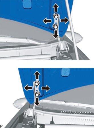 |
Horizontally and vertically adjust the hood.
Loosen the 4 hinge bolts of the hood.
Adjust the clearance between the hood and front fender by moving the hood.
Tighten the 4 hinge bolts after the adjustment.
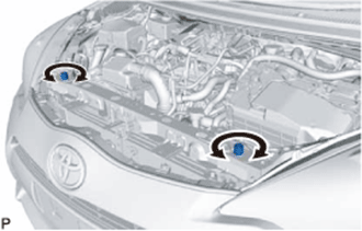 |
Adjust the height of the front end of the hood using the cushion rubbers.
Adjust the 2 cushion rubbers so that the heights of the hood and fender are aligned.
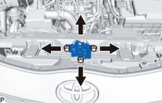 |
Adjust the hood lock.
Loosen the 3 bolts.
Tighten the bolts after adjustment.
Check that the striker can engage with the hood lock smoothly.
| INSPECT FRONT DOOR |
Check that the clearance measurements of areas "a" through "i" are within each standard range.
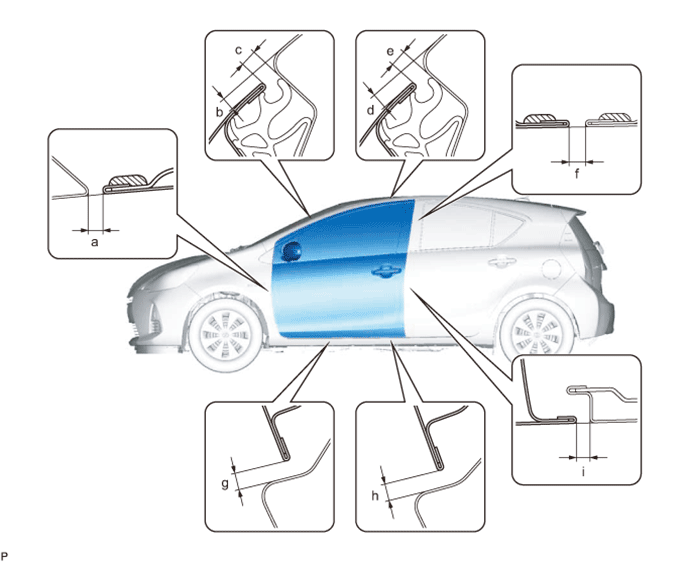
| Area | Measurement | Area | Measurement |
| a | 2.7 to 5.7 mm (0.106 to 0.224 in.) | b | 1.9 to 4.9 mm (0.0748 to 0.193 in.) |
| c | 3.2 to 6.2 mm (0.126 to 0.244 in.) | d | 2.0 to 5.0 mm (0.0787 to 0.197 in.) |
| e | 3.2 to 6.2 mm (0.126 to 0.244 in.) | f | 3.2 to 6.2 mm (0.126 to 0.244 in.) |
| g | 4.2 to 7.2 mm (0.165 to 0.283 in.) | h | 4.2 to 7.2 mm (0.165 to 0.283 in.) |
| i | 3.2 to 6.2 mm (0.126 to 0.244 in.) | - | - |
| ADJUST FRONT DOOR |
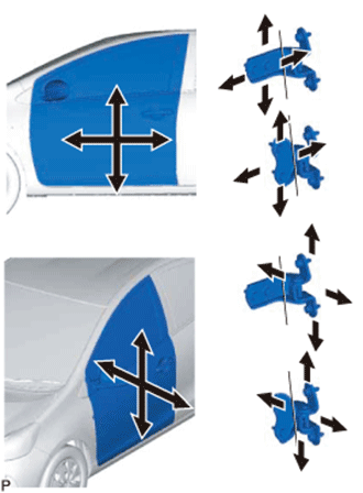 |
Using SST, loosen the hinge bolts on the vehicle body and adjust the door position.
Tighten the body side hinge bolts after the adjustment.
Tighten the door side hinge bolts after the adjustment.
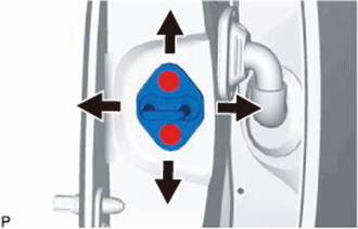 |
Using a T40 "TORX" socket wrench, slightly loosen the striker mounting screws.
Using a brass bar and a hammer, hit the striker to adjust its position.
Using a T40 "TORX" socket wrench, tighten the striker mounting screws after adjustment.
| INSPECT REAR DOOR |
Check that the clearance measurements of areas "a" through "m" are within each standard range.
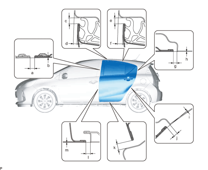
| Area | Measurement | Area | Measurement |
| a | 3.2 to 6.2 mm (0.126 to 0.244 in.) | b | -1.5 to 1.5 mm (-0.0591 to 0.0591 in.) |
| c | 3.2 to 6.2 mm (0.126 to 0.244 in.) | d | 2.1 to 5.1 mm (0.0827 to 0.167 in.) |
| e | 3.2 to 6.2 mm (0.126 to 0.244 in.) | f | 2.3 to 5.3 mm (0.0906 to 0.209 in.) |
| g | 2.7 to 5.7 mm (0.106 to 0.224 in.) | h | -1.5 to 1.5 mm (-0.0591 to 0.0591 in.) |
| i | -1.5 to 1.5 mm (-0.0591 to 0.0591 in.) | j | 2.7 to 5.7 mm (0.106 to 0.224 in.) |
| k | 4.2 to 7.2 mm (0.165 to 0.283 in.) | l | 3.2 to 6.2 mm (0.126 to 0.244 in.) |
| m | -1.5 to 1.5 mm (-0.0591 to 0.0591 in.) | - | - |
| ADJUST REAR DOOR |
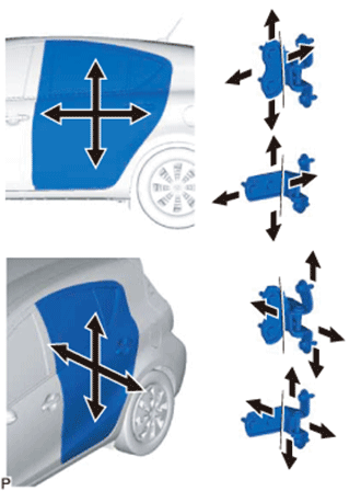 |
Using SST, loosen the hinge bolts on the vehicle body and adjust the door position.
Tighten the hinge bolts on the vehicle body after the adjustment.
Loosen the hinge bolts on the door and adjust the door position.
Tighten the hinge bolts on the door after the adjustment.
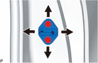 |
Using a T40 "TORX" socket wrench, slightly loosen the striker mounting screws.
Using a brass bar and a hammer, hit the striker to adjust its position.
Using a T40 "TORX" socket wrench, tighten the striker mounting screws after adjustment.
| INSPECT BACK DOOR |
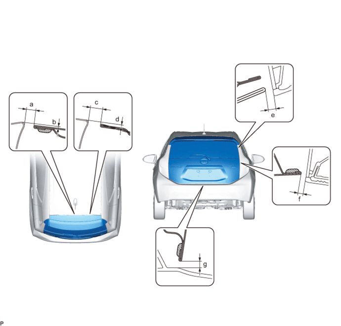
Check that the clearance measurements of areas "a" through "g" are within each standard range.
| Area | Measurement | Area | Measurement |
| a | 5.7 to 8.7 mm (0.244 to 0.343 in.) | b | -0.5 to 2.5 mm (-0.0197 to 0.0197 in.) |
| c | 5.7 to 8.7 mm (0.244 to 0.343 in.) | d | -0.5 to 2.5 mm (-0.0197 to 0.0197 in.) |
| e (Reference) | 5.35 mm (0.211 in.) | f | 3.05 to 7.05 mm (0.120 to 0.278 in.) |
| g | 4.15 to 8.15 mm (0.163 to 0.321 in.) | - | - |
| ADJUST BACK DOOR |
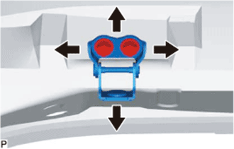 |
Before adjusting the upper end of the back door up and down or left and right, loosen the bolts.
Tighten the body side hinge after adjustment.
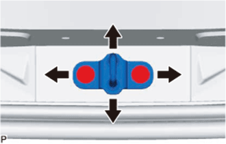 |
Using a T40 "TORX" socket wrench, slightly loosen the striker mounting screws.
Using a brass bar and a hammer, hit the striker to adjust its position.
Using a T40 "TORX" socket wrench, tighten the striker mounting screws after adjustment.