METER / GAUGE SYSTEM > DETAILS |
| OPERATING CONDITION |
Hybrid System Indicator Operation Condition
Hybrid System Indicator is activated when the following conditions are met.
| Condition |
|
| SYSTEM CONTROL |
Seat Belt Warning
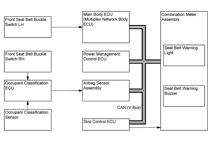
When the ignition switch is ON, this system detects the state of the seat belts based on the signals from the front seat belt buckle switch LH and RH and the occupant classification sensors.
The seat belt warning light located in the combination meter assembly is used for both the driver and front passenger seats.
After the ignition switch is turned ON, if the driver's or front passenger's seat belt has remained unfastened for 1.8 seconds, the front seat belt warning light will flash for 6 seconds. If either of the following conditions is met, the seat belt warning light will continue flashing; the driver's or front passenger's seat belt remains unfastened and the shift lever is in a position other than P for approximately 30 seconds or more, or the driver's or front passenger's seat belt remains unfastened and the seat belt warning buzzer sounds once. Furthermore, if the seat belt is not fastened within approximately 30 seconds from the time the seat belt warning buzzer started sounding periodically, the warning light will commence flashing at short intervals.
If the driver's or front passenger's seat belt is still unfastened even after the ignition switch is turned ON, the seat belt warning buzzer will sound 5 times. From there, if the driver's or front passenger's seat belt remains unfastened and the vehicle speed reaches approximately 20 km/h (12.4 mph), the seat belt warning buzzer will sound once. Furthermore, when approximately 30 seconds has elapsed with the seat belt unfastened, the seat belt warning buzzer will start sounding periodically for 9.6 seconds. If the seat belt is not fastened within this 9.6 seconds, the seat belt warning buzzer will commence sounding at short intervals.
While the seat belt warning light is flashing and the seat belt warning buzzer is sounding, fastening the seat belt will bring the warning light flashing and warning buzzer sounding to a stop.

| FUNCTION |
Combination Meter
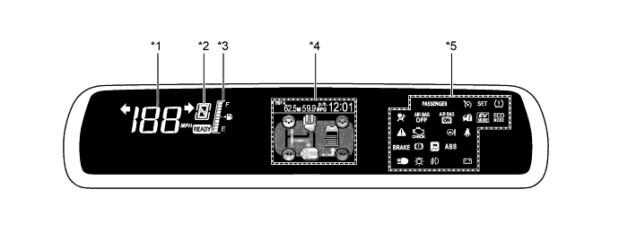
The table below shows the combination meter function:

| Function | Outline | |
| *1 | Speedometer | Digitally displays the vehicle speed signal in MPH or km/h. |
| *2 | Shift Position Indicator | Displays the shift position. |
| *3 | Fuel Gauge | Displays the remaining fuel amount. Also, displays the indication clearly when cornering or driving on a steep slope by using a software application capable of suppressing any indication deviations. |
| *4 | Multi-information Display | Displays the eco drive monitor, odometer, clock and warning messages etc. |
| *5 | Indicator and Warning Lights | Come on or blink to warn the driver. |
| - | Buzzers | Sound to warn the driver. |
Multi-information Display
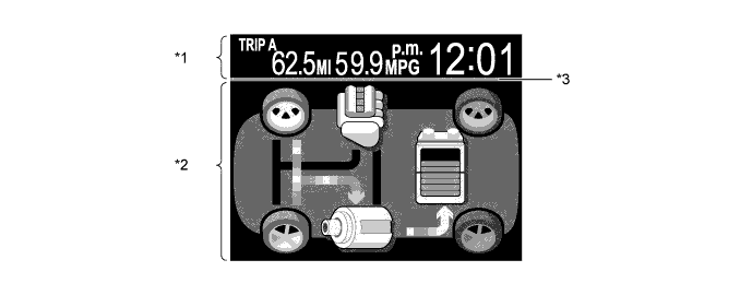
The multi-information display consists of a constant display area (see *1 in the illustration below) and content display area (see *2 in the illustration below).

| Function | Outline | Display Area |
| Opening | System activation animation will be displayed for approximately 3 seconds when the ignition switch is turned ON. | All |
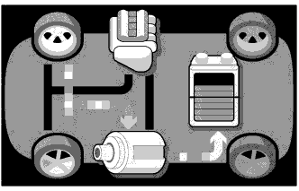
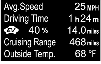
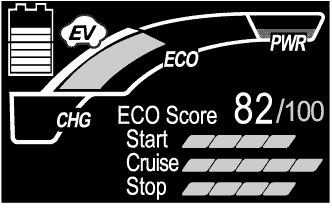
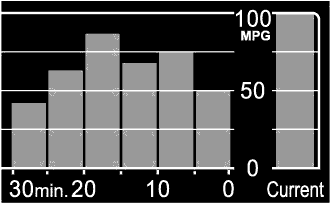
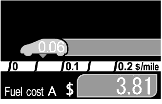
| Eco Drive Monitor | Energy Monitor, Drive Information, ECO Score, 5min Consumption, ECO Savings, ECO Savings Record, Past Record, and Settings & Screen Off can be selected. | *2 |
| Warning Message | Warning messages interrupt the displayed information to warn the diver. | *2 |
| Clock | Time is displayed. | *1 |
| Odometer / Trip Meter | A travel distance is displayed in the odometer, trip meter A and trip meter B respectively. | *1 |
| Average Fuel Consumption | Average fuel consumption is calculated based on the distance the vehicle has run and the amount of fuel the vehicle has consumed, and then the calculation result is displayed. | *1 |
| Ending | System deactivation animation will be displayed for approximately 3 seconds when the ignition switch is turned off. | All |
| Cruising Data | After the ending screen, pieces of information such as a travel distance, time and fuel consumption are displayed. | *2 |
| Color Line |
| *3 |
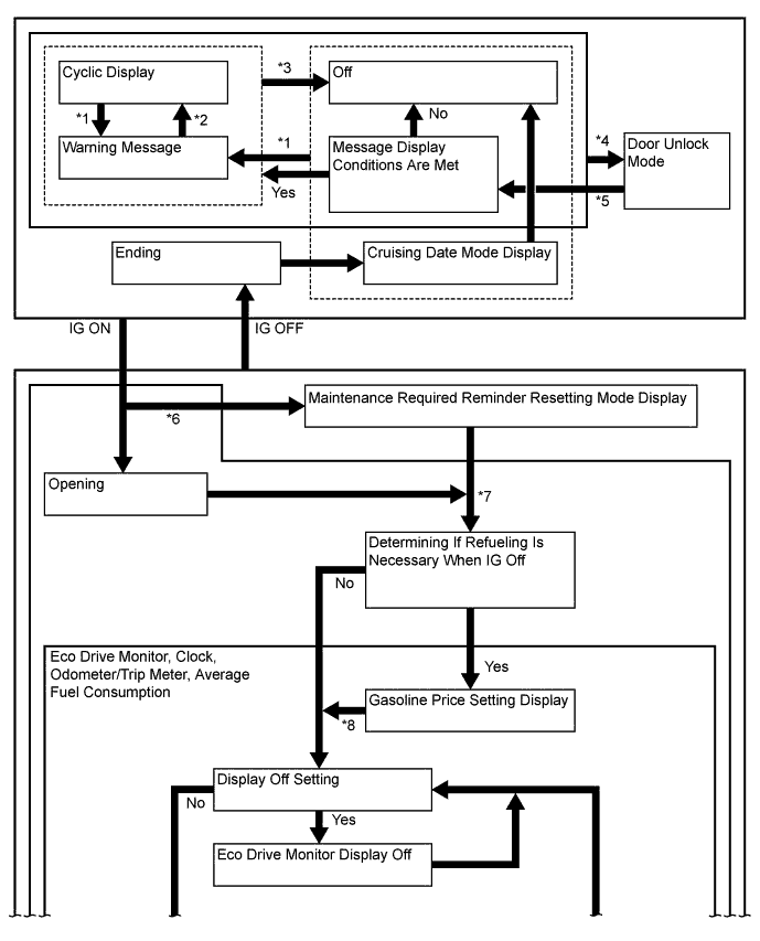
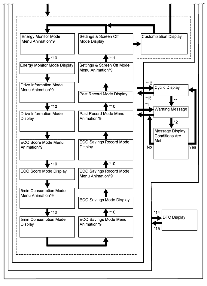
The multi-information display flow can be switched as shown in the flow chart below:


| No. | Transition Condition |
| *1 | Warning message display conditions are met. |
| *2 | All warning message displays have finished or All warning message display conditions are canceled. |
| *3 | Warning message display conditions are canceled. |
| *4 | Door unlock mode transition conditions are met. |
| *5 | Door unlock mode settings have been completed. |
| *6 | Maintenance required reminder accumulation value has reached the predetermined value. |
| *7 | Maintenance required reminder accumulation count has been completed or terminates due to abnormal occurrence. |
| *8 | No switch operation has been made for more than approximately 5 seconds. |
| *9 | The mode the ignition switch was turned off the last time will resume when the ignition switch is turned ON. If the mode was Settings & Screen Off when the ignition switch was turned off the last time, Energy Monitor mode will start from. |
| *10 | The mode display will change after approximately 1.5 seconds of the DISP switch being released. |
| *11 | DISP switch being pressed and held. |
| *12 | The warning message display conditions are met and the DISP switch has not been operated for approximately 10 seconds. |
| *13 | All warning message display conditions are canceled. |
| *14 | DTC display transition conditions are met. |
| *15 | DTC display transition conditions are canceled. |
Eco Drive Monitor
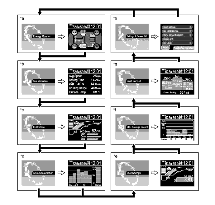
The eco drive monitor is displayed in the following order each time the DISP switch of the steering pad switch assembly is pressed.

| *a | Energy Monitor | *b | Drive Information |
| *c | ECO Score | *d | 5min Consumption |
| *e | ECO Savings | *f | ECO Savings Record |
| *g | Past Record | *h | Settings & Screen Off |
![]() | DISP switch being pressed briefly. | ![]() | Mode display will change after 1.5 seconds of DISP switch being released. |
![]() | DISP switch being pressed and held. | - | - |
The table below shows the eco drive monitor function:
| Display Mode | Display | Outline |
| Energy Monitor | ![]() |
|
| Drive Information | ![]() |
|
| ECO Score | ![]() |
|
| 5min Consumption | ![]() |
|
| ECO Savings*1 | Gasoline Price / Basic*2 | |
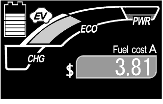
![]() |
| |
| Gasoline Price / Details*2 | ||
![]() |
| |
| Fuel Consumption Comparison*3 / Basic*2 | ||
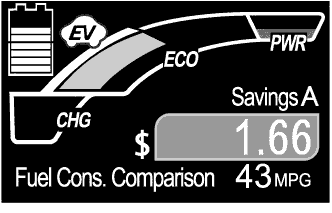
![]() |
| |
| Fuel Consumption Comparison*3 / Details*2 | ||
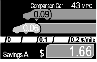
![]() |
| |
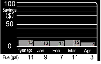
| ECO Savings Record*5 | Gasoline Price | |
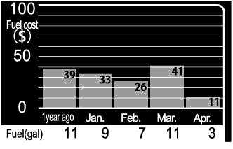
![]() | The gasoline consumption cost for the current month, last month, 2 months ago, 3 months ago, and 1 year ago is shown in bar graph, and the monthly fuel consumption amounts are shown by quantity. | |
| Fuel Consumption Comparison | ||
![]() | The difference of the gasoline consumption costs between the driver's vehicle and comparison vehicle for the current month, last month, 2 months ago, 3 months ago, and 1 year ago is shown in bar graph, and the monthly fuel consumption amounts are shown by quantity. | |
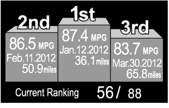
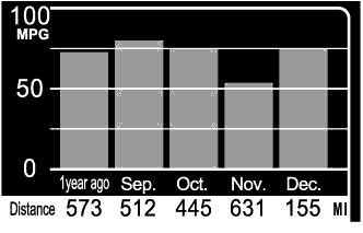
| Past Record*6 | Own Best | |
![]() |
| |
| Monthly Average | ||
![]() |
| |
| Settings & Screen Off | ![]() |
|
Hybrid System Indicator
Hybrid System Indicator will appear when ECO Score mode or ECO Savings mode is selected in the eco drive monitor.
Hybrid System Indicator displays the total of the HV battery and engine output as the hybrid system output.
The scale for Hybrid System Indicator consists of the 3 indicators (Charge, Eco, Power). The role of each indicator is as follows.

| Indicator | Function | |
| *1 | Charge (CHG) | This shows that energy regeneration is occurring. |
| *2 | Eco | This indicator is active while the vehicle is driven eco-friendly. |
| *3 | Eco (Hybrid Eco) | This indicator shows that the vehicle is driven in a manner that promotes frequent motor only operation (Based on the driving conditions, the power management ECU determines if the engine should be stopped to enhance fuel efficiency.). |
| *4 | Power (PWR) | This indicator is on while the drive power is exceeding the eco-friendly driving range (during full power driving etc.). |
Settings & Screen Off
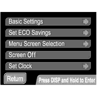
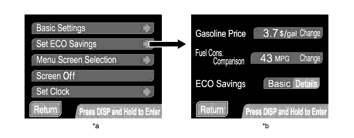
To enter the detail setup screen from the Settings & Screen Off screen, the DISP switch needs to be pressed and held.

| *a | Settings & Screen Off | *b | Set ECO Savings |
![]() | DISP switch being pressed and held. | - | - |
Settings & Screen Off mode has the setup items listed below. For the Basic Settings, Set ECO Savings and Menu Screen Selection, those can be changed when the vehicle is stationary or the vehicle speed is approximately 8 km/h (5 mph) or less.
| Item | Customizing Value | |
| Basic Settings | Date | Adjusts a date. |
| Clock | Adjusts a clock. | |
| Clock Mode | Selects the 12/24 hour time display mode. | |
| Steering Switch | Selects the touch tracer display on/off mode. | |
| Language | Selects the display language. | |
| Set ECO Savings | Gasoline Price | Used to set a gasoline price. |
| Fuel Cons. Comparison | Used to set fuel consumption of a comparison vehicle. | |
| ECO Savings | Selects the ECO Savings Basic/Details mode. | |
| Menu Screen Selection | ECO Savings Record | Selects the ECO Savings Record on/off mode. |
| 5 min. consumption | Selects the 5 min. consumption on/off mode. | |
| Past Record | Changes the Past Record screens. | |
| Screen Off | Turns on/off the eco drive monitor. | |
| Set Clock | Adjusts a clock. | |
Warning Message
When a warning is necessary, the warning display interrupts the display in the multi-information display.
The master warning light may illuminate or blink and the buzzer in the combination meter assembly may sound depending on the item in the multi-information display.
When multiple warning conditions occur at the same time, the highest priority warning message is displayed first. After 2 seconds has elapsed, the next highest priority warning message will be shown. Unless the causes of warnings are removed, the respective warning messages continue.
| Priority | Warning Message | Master Warning Light | Buzzer |
| 1 | MAINTENANCE MODE | - | - |
| CERTIFICATION MODE | - | - | |
| 2 | AUTO POWER OFF TO CONSERVE BATTERY | - | - |
| 3 | SHIFT TO P POSITION*1 | Blinks | Sounds |
| SHIFT TO P POSITION WHEN PARKED | Blinks | Sounds | |
| TRACTION BATTERY PRESERVATION MODE RESTART AFTER SHIFTING THE P POSITION | Blinks | Sounds | |
| N POSITION | Blinks | Sounds | |
| 4 | LOW TRACTION BATTERY CHARGE WHEN NOT IN N POSITION | Blinks | Sounds |
| RELEASE PARKING BRAKE | Blinks | Sounds | |
| KEY NOT DETECTED*1 | Blinks | Sounds | |
| 5 | CHECK HYBRID SYSTEM | Illuminates | Sounds |
| CHECK CRUISE CONTROL SYSTEM*2 | Illuminates | Sounds | |
| ENGINE OIL PRESSURE LOW | Illuminates | Sounds | |
| CHECK HYBRID SYSTEM STOP THE VEHICLE IN A SAFE PLACE IMMEDIATELY | Illuminates | - / Sounds*3 | |
| 6 | TURN POWER OFF*1 | Blinks | Sounds |
| KEY DETECTED IN VEHICLE*1 | Blinks | Sounds | |
| TURN LIGHTS OFF | Blinks | Sounds | |
| MOONROOF OPEN*4 | Blinks | Sounds | |
| DEPRESS BRAKE PEDAL, TOUCH POWER SWITCH WITH KEY*1 | Blinks | Sounds | |
| DEPRESS BRAKE PEDAL AND PUSH POWER SWITCH TO START | Blinks | Sounds | |
| SHIFT TO P POSITION TO START | Blinks | Sounds | |
| 7 | STEERING LOCK ACTIVE | Blinks | Sounds |
| SHIFT TO P POSITION TO START | Blinks | Sounds | |
| 8 | KEY BATTERY LOW*1 | Illuminates | Sounds |
| HYBRID SYSTEM OVER HEAT OUTPUT POWER IS LIMITED | Illuminates | Sounds | |
| 9 | MAINTENANCE REQUIRED SOON | - | - |
| MAINTENANCE REQUIRED | - | - | |
| RESETTING MAINTENANCE DATA | - | - | |
| RESETTING OF MAINTENANCE DATA INCOMPLETE | - | - | |
| POWER ON | - | - | |
| EV MODE CURRENTLY NOT AVAILABLE | - | Sounds | |
| EV MODE NOT AVAILABLE WARMING UP | - | Sounds | |
| EV MODE NOT AVAILABLE LOW BATTERY | - | Sounds | |
| EV MODE NOT AVAILABLE EXCESSIVE SPEED | - | Sounds | |
| EV MODE NOT AVAILABLE EXCESSIVE ACCELERATION | - | Sounds | |
| EV MODE DEACTIVATED | - | Sounds | |
| EV MODE DEACTIVATED LOW BATTERY | - | Sounds | |
| EV MODE DEACTIVATED EXCESSIVE SPEED | - | Sounds | |
| EV MODE DEACTIVATED EXCESSIVE ACCELERATION | - | Sounds |
Buzzer
The table below shows the warning and reminder functions of the buzzer in the combination meter assembly:
| Priority | Item | Priority | Item |
| 1 | READY | 2 | Driver Side Seat Belt Warning (a maximum of 5 times) |
| 3 | Driver Side Seat Belt Warning (Once) | 4 | Passenger Side Seat Belt Warning (Once) |
| 5 | Seat Belt Warning (Level 2) | 6 | Seat Belt Warning (Level 1) |
| 7 | Brake System Warning | 8 | EPS Warning |
| 9 | Door Open Warning When Not in P Position*1 | 10 | Smart Key System Warning (Intermittent)*1 |
| 11 | Key Reminder | 12 | Brake Operation Active Check Indication |
| 13 | Hill-start Assist Control Indication (Reset) | 14 | Hill-start Assist Control Indication (Set) |
| 15 | Smart Key System Warning (Intermittent 2)*1 | 16 | Smart Key System Warning (Once)*1 |
| 17 | Low Fuel Indicator | 18 | Multi-information Display Warning |
| 19 | Accelerator Depression with Neutral (N) Selected | 20 | Hybrid System Warning (Intermittent) |
| 21 | HV Battery Low Warning | 22 | Hybrid System Warning (Once) |
| 23 | HV Battery Charge Request | 24 | Hybrid System Overheat Warning |
| 25 | P Position Request at Start | 26 | Immobiliser Certification Reminder |
| 27 | Parking Brake Engaged Warning | 28 | Door Open while Driving Warning |
| 29 | EV Drive Mode Reject Warning | 30 | Light Reminder |
| 31 | Sliding Roof Warning*2 | 32 | Turn Flasher Sound |
Maintenance Required Reminder
A maintenance required reminder will appear to remind the driver to have maintenance performed based on the vehicle driving distance.
The combination meter assembly calculates the vehicle driving distance based on signals from the skid control ECU.
There are 2 types of warnings: one is displayed when the vehicle driving distance is 4500 miles or more since the last time the system was reset, and the other is displayed when the driving distance is 5000 miles or more.
The maintenance required reminder method has the following equipment:
| Reminder Method | 4500 miles or more | 5000 miles or more |
| Maintenance required reminder message on the multi-information display | "MAINTENANCE REQUIRED SOON" appears for approximately 16 seconds. | "MAINTENANCE REQUIRED" warning remains on. |
After maintenance, the accumulated vehicle travel distance memorized in the combination meter assembly should be reset to zero using the TRIP switch.
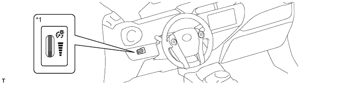
Light Control Rheostat
The brightness of the instrument panel can be adjusted when the taillights are turned on.
The nighttime brightness level of the combination meter assembly can be adjusted between 1% and 12.5% for the daytime brightness level of 100%, by using a dial-type switch, and the indicator lights on the combination meter assembly can be turned off by further decreasing the brightness level.

| *1 | Light Control Rheostat | - | - |
| CONSTRUCTION |
Steering Pad Switch Assembly
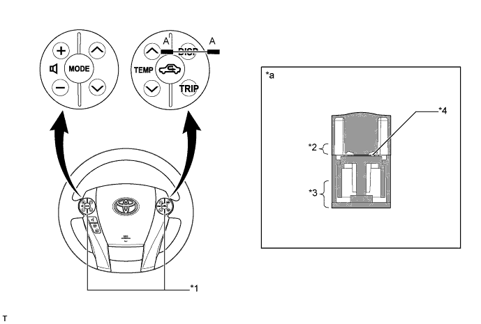
A touch sensor is provided on the following frequently used switches such as the multi-information display, audio system and air conditioning system switches. The touch tracer display is displayed when any of the switches is touched by the driver's finger, and the switch is activated when pressed.
| Steering Pad Switch Assembly | Touch Sensor | |
| Audio System | Volume Switch (+) | Equipped |
| Volume Switch (-) | Equipped | |
| MODE Switch | Equipped | |
| Seek Switch (Up) | Equipped | |
| Seek Switch (Down) | Equipped | |
| Multi-information Display | TRIP Switch | Equipped |
| DISP Switch | Equipped | |
| Air Conditioning System | Air Inlet Control Switch | Equipped |
| TEMP Switch (Up) | Equipped | |
| TEMP Switch (Down) | Equipped | |
| Bluetooth Hands-free System | Voice Switch | Not equipped |
| On Hook Switch | Not equipped | |
| Off Hook Switch | Not equipped | |

| *1 | Steering Pad Switch Assembly | *2 | Touch Switch Area |
| *3 | Function Switch Area | *4 | Touch Sensor |
| *a | A-A Cross Section | - | - |