 |
Rotate the control shaft lever clockwise until it stops, and then from that position rotate it counterclockwise by 2 notches to set it to the N position.
| *a | P Position |
| *b | N Position |
TRANSMISSION CONTROL CABLE > INSTALLATION |
| 1. INSTALL TRANSMISSION CONTROL CABLE ASSEMBLY |
Pass the transmission control cable into the vehicle and install the transmission control cable assembly to the body using the 3 nuts.
Install the transmission control cable assembly to the transmission control cable clamp and transmission control cable support.
Install the transmission control cable assembly to the No. 1 transmission control cable bracket with a new clip.
|
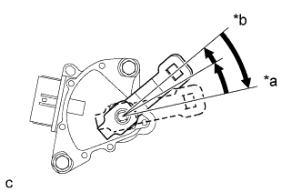
Rotate the control shaft lever clockwise until it stops, and then from that position rotate it counterclockwise by 2 notches to set it to the N position.
| *a | P Position |
| *b | N Position |
Install the transmission control cable assembly onto the transmission control shaft lever with the nut.
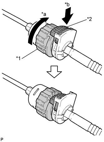 |
Rotate the nut of the transmission control cable assembly approximately 180° in the direction shown in the illustration, and while holding the nut, push in the lock.
| *1 | Nut |
| *2 | Lock |
| *a | Rotate Approximately 180° |
| *b | Push In |
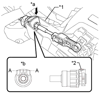 |
Install the transmission control cable assembly to the shift lever plate.
| *1 | Shift Lever Plate |
| *2 | Lock |
| *a | Install |
| *b | Projecting Part |
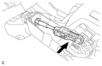 |
Confirm that the shift lever is in N, and then install the cable end to the shift lever assembly.
| 2. ADJUST SHIFT LEVER POSITION |
Apply the parking brake and move the shift lever to N.
Remove the rear console box assembly (Click here).
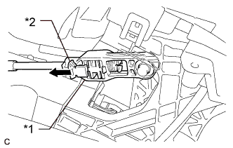 |
Slide the adjuster case cover in the direction shown by the arrow.
| *1 | Adjuster Case |
| *2 | Adjuster Case Cover |
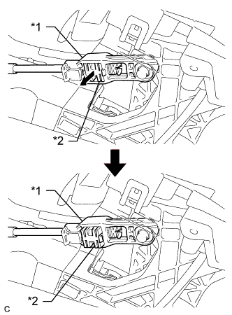 |
Using a precision screwdriver, pull out the lock piece of the adjuster case.
| *1 | Adjuster Case |
| *2 | Lock Piece |
Using your fingers, gently pull the cable rod towards the rear of the vehicle to remove backlash.
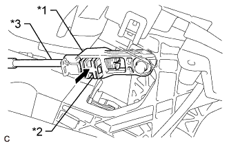 |
Push in the lock piece of the adjuster case to lock it.
| *1 | Adjuster Case |
| *2 | Lock Piece |
| *3 | Cable Rod |
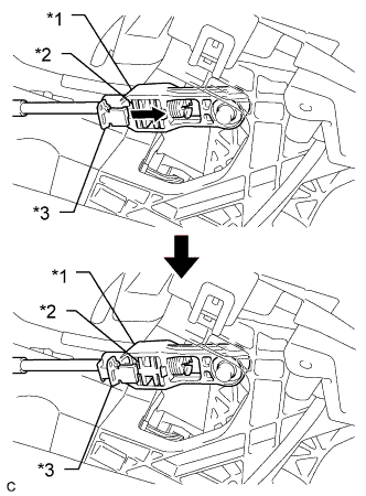 |
Move the adjuster case cover in the direction shown by the arrow.
| *1 | Adjuster Case |
| *2 | Lock Piece |
| *3 | Adjuster Case Cover |
Install the rear console box assembly (Click here).
| 3. INSTALL FRONT NO. 1 FLOOR HEAT INSULATOR SUB-ASSEMBLY |
Install the No. 1 floor heat insulator sub-assembly with the 2 bolts and nut.
| 4. INSTALL FRONT EXHAUST PIPE ASSEMBLY |
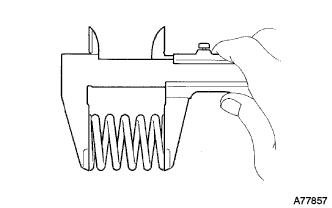 |
Using a vernier caliper, measure the free length of the compression springs.
| Minimum (front) | 41.5 mm (1.64 in.) |
| Minimum (rear) | 38.5 mm (1.52 in.) |
Fully insert 2 new gaskets to the exhaust manifold converter and front exhaust pipe assembly.
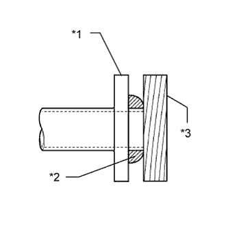 |
Using a plastic hammer and wooden block, tap in each new gasket until its surface is flush with the exhaust manifold and front exhaust pipe assembly.
| *1 | Exhaust Manifold and Front Exhaust Pipe Assembly |
| *2 | Gasket |
| *3 | Wooden Block |
Connect the front exhaust pipe assembly to the 3 exhaust pipe supports.
Install the front exhaust pipe assembly with the 2 compression springs and 2 bolts.
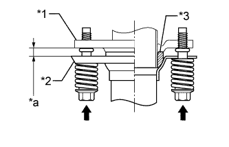 |
| *1 | Exhaust Manifold |
| *2 | Front Exhaust Pipe Assembly |
| *3 | Gasket |
| *a | Space between flanges: 8.5 mm (0.335 in.) |
Install the front exhaust pipe assembly with the 2 compression springs and 2 bolts.
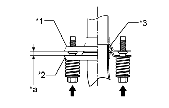 |
| *1 | Tail Exhaust Pipe Assembly |
| *2 | Front Exhaust Pipe Assembly |
| *3 | Gasket |
| *a | Space between flanges: 6.5 mm (0.256 in.) |
Connect the 2 heater water hoses.
| 5. INSTALL REAR CONSOLE BOX ASSEMBLY |
| 6. ADD COOLANT (for Engine) |
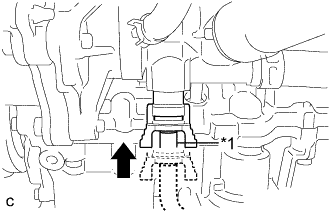 |
Insert the engine drain cock plug.
| *1 | Hose |
Disconnect the hose from the engine drain cock plug.
Install the stop ring.
Tighten the radiator drain cock plug by hand.
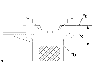 |
Slowly fill the radiator with TOYOTA Super Long Life Coolant (SLLC) from the water filler. (Coolant level should be within 20 mm (0.787 in.) from the filler tube end.)
| *a | Filler Tube End |
| *b | Coolant Level |
| *c | 20 mm |
Remove the reserve tank cap.
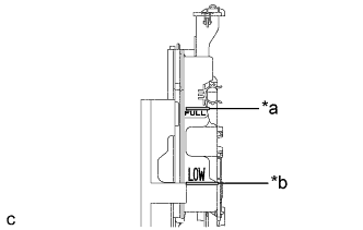 |
Slowly pour coolant into the radiator reserve tank assembly until it reaches the full line.
| *a | Full Line |
| *b | Low Line |
Squeeze the No. 1 and No. 2 radiator hoses several times by hand, and then check the level of the coolant.
If the coolant level is low, add coolant.
Install the water filler cap sub-assembly and reserve tank cap.
Put the engine in inspection mode (Click here).
Bleed air from the cooling system.
Warm up the engine until the thermostat opens. While the thermostat is open, circulate the coolant for several minutes.
Squeeze the No. 1 and No. 2 radiator hoses several times by hand to bleed air.
Stop the engine and wait until the engine coolant cools down.
Add engine coolant to the full line on the radiator reserve tank assembly.
| 7. INSPECT FOR COOLANT LEAK |
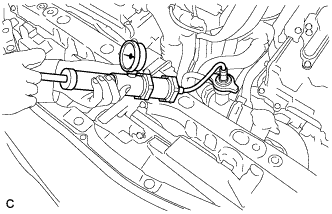 |
Fill the radiator with coolant and attach a radiator cap tester.
Put the engine in inspection mode (Click here).
Warm up the engine.
Using a radiator cap tester, increase the pressure inside the radiator to 108 kPa (1.1 kgf/cm2, 16 psi), and check that the pressure does not drop.
If the pressure drops, check the hoses, radiator, engine water pump, front exhaust pipe assembly and engine coolant temperature sensor for leaks. If no external leaks are found, check the heater core, cylinder block and cylinder head.
| 8. INSPECT SHIFT LEVER POSITION |
While moving the shift lever from N to each position, check that the lever moves smoothly and that the shift position indicator comes on properly according to the shift lever position.
Turn the ignition switch to on (READY) and check the following:
When the shift lever is moved to D, the vehicle moves forward.
When the shift lever is moved to R, the vehicle moves in reverse.
| 9. INSPECT FOR EXHAUST GAS LEAK |