 |
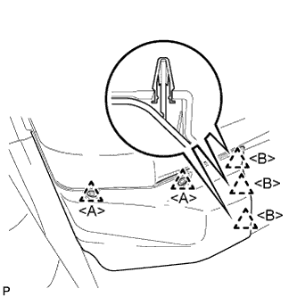
Using a clip remover, remove the 2 clips <A>.
REAR AIRBAG SENSOR > REMOVAL |
| 1. PRECAUTION |
| 2. REMOVE REAR SEAT HEADREST ASSEMBLY |
| 3. REMOVE REAR CENTER SEAT HEADREST ASSEMBLY |
| 4. REMOVE FRONT FLOOR COVER RH |
|
Using a clip remover, remove the 2 clips <A>.
Disengage the 3 clips <B>.
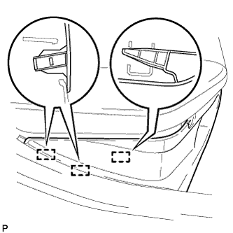 |
Disengage the 3 guides and remove the front floor cover RH.
| 5. REMOVE FRONT FLOOR COVER LH |
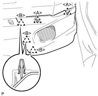 |
Using a clip remover, remove the 2 clips <A>.
Disengage the 3 clips <B>.
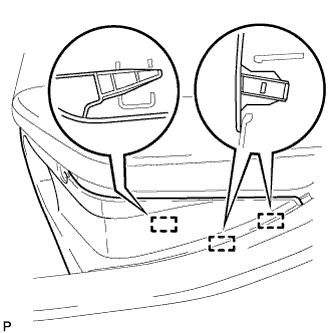 |
Disengage the 3 guides and remove the front floor cover LH.
| 6. REMOVE FRONT CENTER FLOOR COVER |
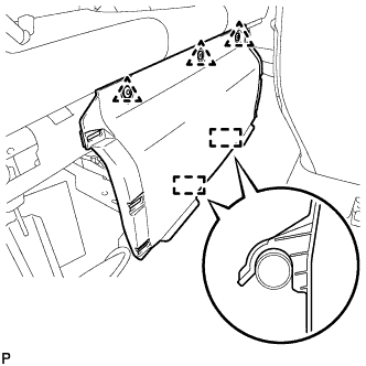 |
Using a clip remover, remove the 3 clips.
Disengage the 2 guides and remove the front center floor cover.
| 7. REMOVE REAR SEAT CUSHION ASSEMBLY |
| 8. REMOVE REAR SEATBACK ASSEMBLY |
| 9. DISCONNECT CABLE FROM NEGATIVE AUXILIARY BATTERY TERMINAL |
| 10. REMOVE REAR DOOR SCUFF PLATE |
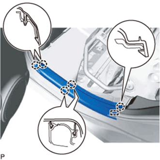 |
Disengage the 5 claws and guide and remove the rear door scuff plate LH.
| 11. DISCONNECT REAR DOOR OPENING TRIM WEATHERSTRIP |
| 12. REMOVE REAR FLOOR MAT ASSEMBLY |
Remove the rear floor mat assembly.
| 13. REMOVE SPARE WHEEL CUSHION |
Remove the 2 spare wheel cushions.
| 14. REMOVE PACKAGE TRAY TRIM PANEL ASSEMBLY (w/ Package Tray Trim) |
Remove the package tray trim panel assembly.
| 15. REMOVE REAR DECK TRIM COVER |
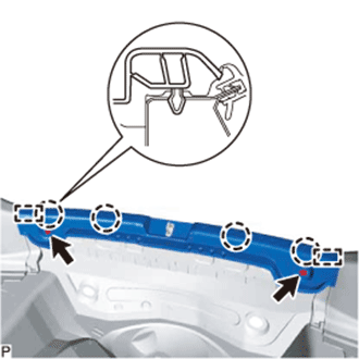 |
Remove the 2 clips.
Disengage the 4 claws and 2 guides, and remove the rear deck trim cover.
| 16. DISCONNECT REAR SEAT 3 POINT TYPE OUTER BELT ASSEMBLY |
Remove the bolt.
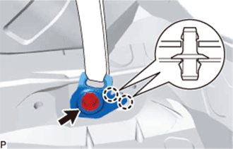 |
Disengage the 2 claws and disconnect the floor anchor of the rear seat 3 point type outer belt assembly.
| 17. REMOVE NO. 1 LUGGAGE COMPARTMENT LIGHT ASSEMBLY (w/ Luggage Compartment Room Light) |
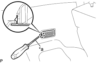 |
Using a screwdriver with its tip wrapped with protective tape, disengage the claw.
| *a | Protective Tape |
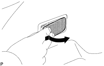 |
Remove the No. 1 luggage compartment light assembly as shown in the illustration.
Disconnect the connector and remove the No. 1 luggage compartment light assembly.
| 18. REMOVE DECK TRIM SIDE PANEL ASSEMBLY |
| 19. REMOVE SIDE NO. 2 AIRBAG SENSOR ASSEMBLY |
Check that the ignition switch is off.
Check that the cable is disconnected from the negative (-) auxiliary battery terminal.
Disconnect the connector from the side No. 2 airbag sensor assembly.
Push down the white housing lock and slide the yellow CPA. (At this time, the connector cannot be disconnected yet.)
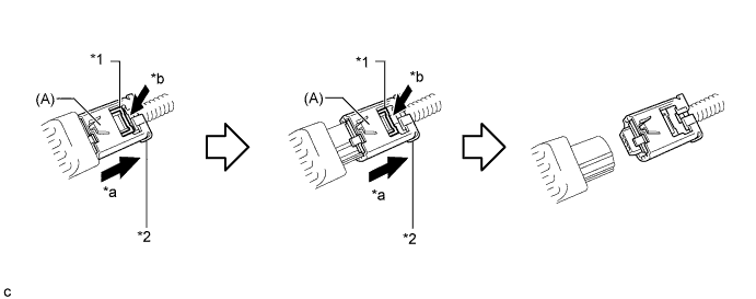
| *1 | White Housing Lock | *2 | Yellow CPA |
| *a | Slide | *b | Push |
Push down the white housing lock again and disconnect the connector.
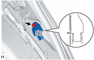 |
Remove the bolt and side No. 2 airbag sensor assembly from the vehicle body.
After disconnecting the connector, check that the position of the white housing lock is correct as shown in the illustration.
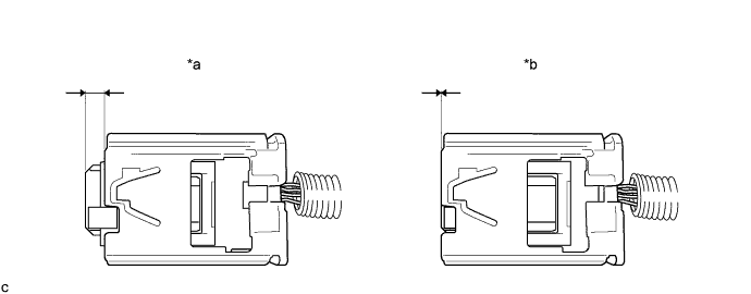
| *a | Correct | *b | Incorrect |