
TIRE PRESSURE WARNING SYSTEM > TERMINALS OF ECU |
| CHECK TIRE PRESSURE WARNING ECU AND RECEIVER |
| *A | w/ Smart Key System | *B | w/o Smart Key System |
Measure the voltage and resistance according to the value(s) in the table below. If the result is not as specified, the ECU may be malfunctioning.
| Terminal No. (Symbol) | Wiring Color | Terminal Description | Condition | Specified Condition |
| M17-1 (IG) - M17-12 (GND)*1 M20-1 (IG) - M20-12 (GND)*2 | L - W-B | IG power source | Ignition switch ON | 10 to 16 V |
| M17-3 (CLSW) - M17-12 (GND)*1 M20-3 (CLSW) - M20-12 (GND)*2 | B - W-B | Tire pressure warning reset switch |
| Below 1.5 V |
| 8 to 15 V | |||
| M17-4 (RDA) - M17-12 (GND)*1 M20-4 (RDA) - M20-12 (GND)*2 | R - W-B | Output signals | Ignition switch ON | Pulse generation (see waveform 1) |
| M17-5 (PRG) - M17-12 (GND)*1 M20-5 (PRG) - M20-12 (GND)*2 | W - W-B | Input signals | Ignition switch ON | Pulse generation (see waveform 1) |
| M17-12 (GND) - Body ground*1 M20-12 (GND) - Body ground*2 | W-B - Body ground | Ground | Always | Below 1 Ω |
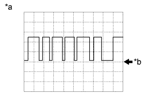 |
Using an oscilloscope, check waveform 1.
| *a | Example |
| *b | GND |
| Item | Contents |
| Terminal | M17-4 (RDA) - M17-12 (GND)*1 M20-4 (RDA) - M20-12 (GND)*2 M17-5 (PRG) - M17-12 (GND)*1 M20-5 (PRG) - M20-12 (GND)*2 |
| Tool setting | 5 V/DIV, 50 μs./DIV. |
| Vehicle condition | Ignition switch ON |