 |
Lay a strip of Plastigage across the crank pin.
| *1 | Plastigage |
CYLINDER BLOCK > INSPECTION |
| 1. INSPECT CONNECTING ROD OIL CLEARANCE |
Clean the crank pin and connecting rod bearing.
Install the crankshaft .
Install the connecting rod bearing .
Install the connecting rod sub-assembly .
|
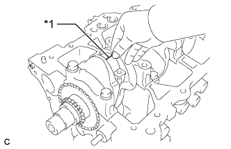
Lay a strip of Plastigage across the crank pin.
| *1 | Plastigage |
Install the connecting rod cap .
Remove the connecting rod cap .
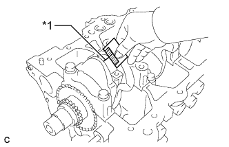 |
Measure the Plastigage at its widest point.
| *1 | Plastigage |
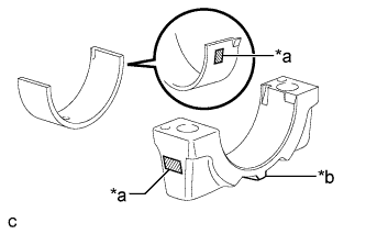 |
If the connecting rod oil clearance is greater than the maximum, select and replace the connecting rod bearings. If necessary, use an undersized connecting rod bearing.
| *a | Number Mark |
| *b | Front Mark |
| Number Mark | Connecting Rod External Diameter | Center Bearing Thickness | Oil Clearance |
| 1 | 43.000 to 43.006 mm (1.6929 to 1.6931 in.) | 1.491 to 1.494 mm (0.058701 to 0.058818 in.) | 0.012 to 0.032 mm (0.000472 to 0.00125 in.) |
| 2 | 43.006 to 43.014 mm (1.6931 to 1.6935 in.) | 1.494 to 1.497 mm (0.058818 to 0.058937in.) | 0.012 to 0.034 mm (0.000472 to 0.00134 in.) |
| 3 | 43.014 to 43.020 mm (1.6935 to 1.6937 in.) | 1.497 to 1.500 mm (0.058937 to 0.059055 in.) | 0.014 to 0.034 mm (0.000551 to 0.00134 in.) |
| U/S 0.25 | 43.000 to 43.020 mm (1.6929 to 1.6937 in.) | 1.610 to 1.614 mm (0.063386 to 0.063543 in.) | 0.012 to 0.034 mm (0.000472 to 0.00134 in.) |
| 2. INSPECT CRANKSHAFT OIL CLEARANCE |
Clean the crank journal and crankshaft bearing cap.
Install the crankshaft bearing .
Install the crankshaft .
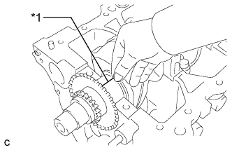 |
Lay a strip of Plastigage across each journal.
| *1 | Plastigage |
Install the crankshaft bearing cap .
Remove the crankshaft bearing cap .
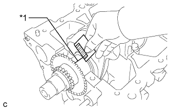 |
Measure the Plastigage at its widest point.
| *1 | Plastigage |
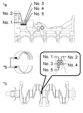 |
If the crankshaft oil clearance is greater than the maximum, select and replace the crankshaft bearing. If necessary, use an undersized main bearing.
| *a | Cylinder Block Number |
| *b | Bearing Number |
| *c | Crank Journal Number |
| Number | Cylinder Block Diameter | Crankshaft Journal Diameter |
| 0 | 50.000 to 50.003 mm (1.9685 to 1.9686 in.) | 45.998 to 46.000 mm (1.8109 to 1.8110 in.) |
| 1 | 50.003 to 50.005 mm (1.9686 to 1.9687 in.) | 45.996 to 45.998 mm (1.81086 to 1.81094 in.) |
| 2 | 50.005 to 50.007 mm (1.9687 to 1.9688 in.) | 45.994 to 45.996 mm (1.8108 to 1.8109 in.) |
| 3 | 50.007 to 50.010 mm (1.9688 to 1.9689 in.) | 45.992 to 45.994 mm (1.8107 to 1.8108 in.) |
| 4 | 50.010 to 50.012 mm (1.9689 to 1.9690 in.) | 45.990 to 45.992 mm (1.8106 to 1.8107 in.) |
| 5 | 50.012 to 50.014 mm (1.9690 to 1.9691 in.) | 45.988 to 45.990 mm (1.8105 to 1.8106 in.) |
| 6 | 50.014 to 50.016 mm (1.96905 to 1.96913 in.) | - |
| Cylinder Block Number + Crank Journal Number | Bearing Number | Center Bearing Thickness | Oil Clearance |
| 0 to 2 | 1 | 1.992 to 1.995 mm (0.0784 to 0.0785 in.) | 0.010 to 0.026 mm (0.000394 to 0.00102 in.) |
| 3 to 5 | 2 | 1.995 to 1.998 mm (0.0785 to 0.0787 in.) | 0.010 to 0.026 mm (0.000394 to 0.00102 in.) |
| 6 to 8 | 3 | 1.998 to 2.001 mm (0.0787 to 0.0788 in.) | 0.010 to 0.026 mm (0.000394 to 0.00102 in.) |
| 9 to 11 | 4 | 2.001 to 2.004 mm (0.0788 to 0.0789 in.) | 0.010 to 0.026 mm (0.000394 to 0.00102 in.) |
| - | U/S 0.25 | 2.111 to 2.117 mm (0.0831 to 0.0833 in.) | 0.010 to 0.026 mm (0.000394 to 0.00102 in.) |
| 3. INSPECT CYLINDER BLOCK FOR WARPAGE |
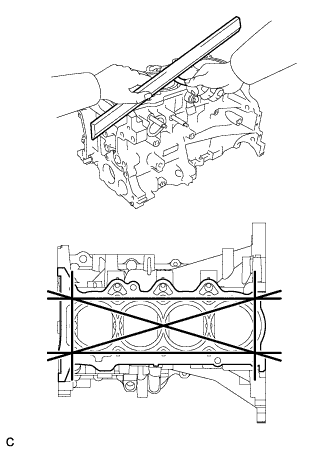 |
Using a precision straightedge and feeler gauge, check the cylinder block surface that contacts the cylinder head gasket for warpage.
| 4. INSPECT CYLINDER BORE |
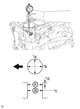 |
Using a cylinder gauge, measure the cylinder bore diameter at positions A and B in the thrust and axial directions.
| *a | Thrust Direction |
| *b | Axial Direction |
| *c | Center |
| *d | 10 mm (0.394 in.) |
 | Engine Front |
| 5. INSPECT CONNECTING ROD SUB-ASSEMBLY |
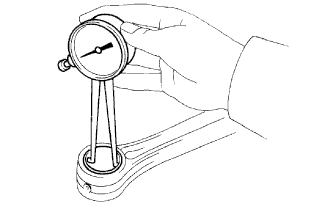 |
Using a caliper gauge, measure the inside diameter of the connecting rod sub-assembly.
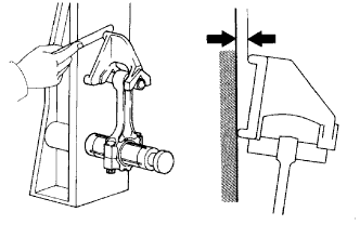 |
Using a connecting rod aligner and feeler gauge, check the connecting rod sub-assembly alignment.
Check for misalignment.
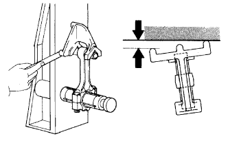 |
Check for twist.
| 6. INSPECT PISTON SUB-ASSEMBLY AND PISTON PIN |
Clean the piston sub-assembly and piston pin.
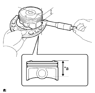 |
Using a micrometer, measure the piston diameter at right angles to the piston pin hole, and at a point 37 mm (1.46 in.) from the piston bottom.
| *a | 37 mm (1.46 in.) |
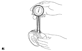 |
Using a caliper gauge, measure the piston pin hole diameter of the piston.
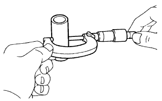 |
Using a micrometer, measure the piston pin diameter.
Subtract the piston pin diameter measurement from the piston pin hole diameter measurement.
| 7. INSPECT PISTON OIL CLEARANCE |
Subtract the piston diameter measurement from the cylinder bore diameter measurement.
| 8. INSPECT RING GROOVE CLEARANCE |
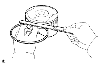 |
Using a feeler gauge, measure the ring groove clearance between a new piston ring and the wall of the ring groove.
| Item | Specified Condition |
| No. 1 ring | 0.02 to 0.07 mm (0.000787 to 0.00276 in.) |
| No. 2 ring | 0.02 to 0.06 mm (0.000787 to 0.00236 in.) |
| Oil ring | 0.07 to 0.13 mm (0.00276 to 0.00512 in.) |
| 9. INSPECT PISTON RING END GAP |
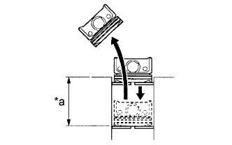 |
Using a piston, push the piston ring a little beyond the bottom of the ring travel, 110 mm (4.33 in.) from the top of the cylinder block.
| *a | 110 mm (4.33 in.) |
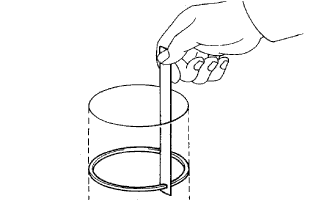 |
Using a feeler gauge, measure the ring end gap.
| Item | Standard | Maximum |
| No. 1 ring | 0.18 to 0.28 mm (0.00709 to 0.0110 in.) | 0.59 mm (0.0232 in.) |
| No. 2 ring | 0.28 to 0.43 mm (0.0110 to 0.0169 in.) | 1.18 mm (0.0465 in.) |
| Oil ring | 0.10 to 0.35 mm (0.00394 to 0.0138 in.) | 1.13 mm (0.0445 in.) |
| 10. INSPECT CONNECTING ROD BOLT |
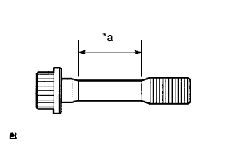 |
Using a vernier caliper, measure the diameter of the connecting rod bolt in the area shown in the illustration.
| *a | Measurement Area |
| 11. INSPECT CRANKSHAFT |
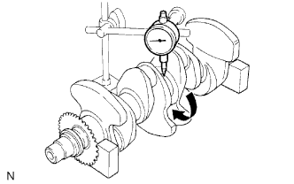 |
Using a dial indicator and V-blocks, measure the runout as shown in the illustration.
Inspect the diameter.
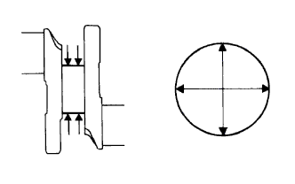 |
Using a micrometer, measure the diameter of each main journal as shown in the illustration.
Calculate the taper and out-of-round of the main journal.
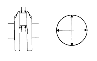 |
Using a micrometer, measure the diameter of each crank pin as shown in the illustration.
Calculate the taper and out-of-round of the crank pin.
Wrap the chain sub-assembly around the timing sprocket.
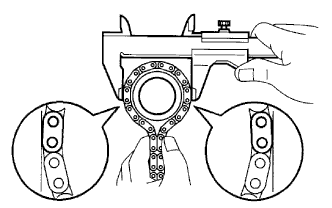 |
Using a vernier caliper, measure the diameter of the timing sprocket with the chain sub-assembly.
| 12. INSPECT CRANKSHAFT BEARING CAP SET BOLT |
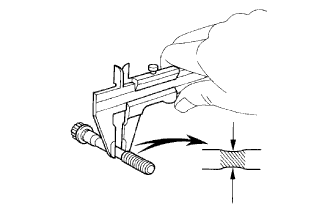 |
Using a vernier caliper, measure the diameter of the crankshaft bearing cap set bolt at the thinnest point.