 |
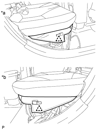
Using a clip remover, disengage the 2 clips.
| *a | RH Side |
| *b | LH Side |
HV BATTERY > REMOVAL |
| 1. PRECAUTION |
| 2. CHECK FOR DTCS |
Check for DTCs (Click here).
| 3. REMOVE SERVICE PLUG GRIP |
| 4. REMOVE REAR SEAT CUSHION ASSEMBLY |
|
Using a clip remover, disengage the 2 clips.
| *a | RH Side |
| *b | LH Side |
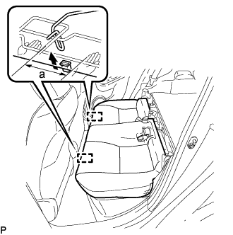 |
Disengage the hook of the rear seat cushion assembly from the vehicle body as shown in the illustration.
| a | 100 mm (3.94 in.) or less |
Choose a hook to disengage first. Place your hands near the hook as shown in the illustration. Then lift the seat cushion to disengage the hook.
Repeat the step above for the other hook.
Remove the rear seat cushion assembly.
| 5. REMOVE REAR SEAT CUSHION LEG SUB-ASSEMBLY |
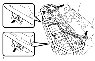 |
Remove the 4 bolts and rear seat cushion leg sub-assembly.
| 6. REMOVE INVERTER TERMINAL COVER |
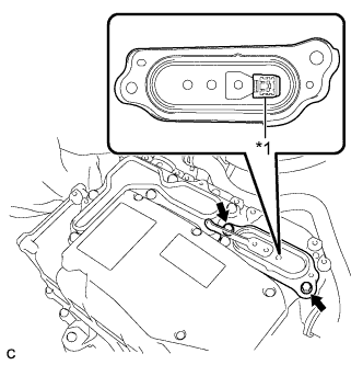 |
Remove the 2 bolts and inverter terminal cover.
| *1 | Interlock Connector |
| 7. REMOVE INVERTER COVER |
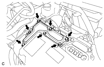 |
Remove the 7 bolts and inverter cover.
| 8. CHECK TERMINAL VOLTAGE |
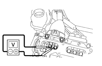 |
Using a voltmeter, measure the voltage between the terminals of the 2 phase connectors.
| 9. INSTALL INVERTER COVER |
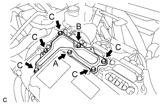 |
Temporarily install the inverter cover with the 7 bolts to the inverter with converter assembly.
Fully tighten the bolt (A).
Fully tighten the bolt (B).
Fully tighten the 5 bolts (C).
| 10. INSTALL INVERTER TERMINAL COVER |
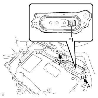 |
Temporarily install the inverter terminal cover with the 2 bolts to the inverter with converter assembly.
| *1 | Interlock Connector |
Fully tighten the bolt (A).
Fully tighten the bolt (B).
| 11. REMOVE NO. 1 HYBRID BATTERY EXHAUST DUCT |
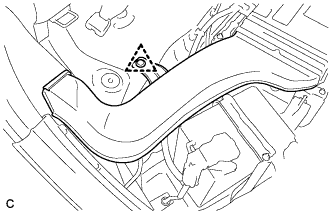 |
Remove the clip and No. 1 hybrid exhaust duct.
| 12. REMOVE BATTERY COOLING BLOWER ASSEMBLY |
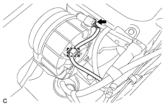 |
Disconnect the battery cooling blower assembly connector and clamp.
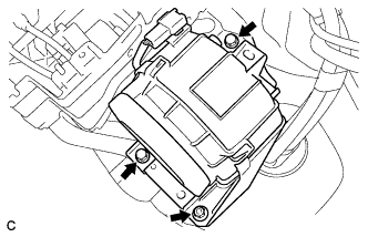 |
Remove the 2 bolts, nut and battery cooling blower assembly.
| 13. REMOVE NO. 1 HYBRID VEHICLE BATTERY COVER PANEL LH |
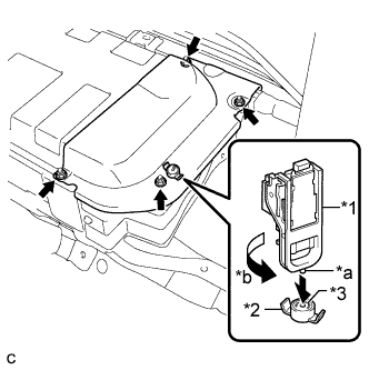 |
Using the service plug grip, remove the battery cover lock striker.
| *1 | Service Plug Grip |
| *2 | Battery Cover Lock Striker |
| *3 | Button |
| *a | Projection |
| *b | Turn |
Remove the 4 nuts and No. 1 hybrid vehicle battery cover panel LH.
| 14. REMOVE NO. 3 INDOOR ELECTRICAL KEY ANTENNA ASSEMBLY |
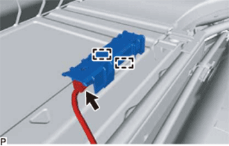 |
Disengage the 2 clamps.
Disconnect the connector and remove the No. 3 indoor electrical key antenna assembly.
| 15. REMOVE WIRE HARNESS |
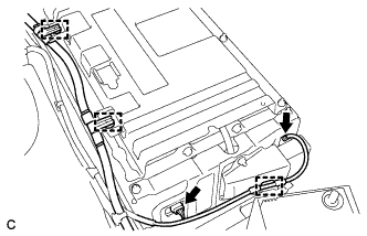 |
Disconnect the 2 connectors and 3 clamps as shown in the illustration.
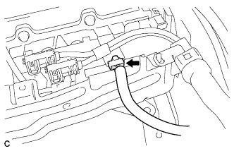 |
Disconnect the connector as shown in the illustration.
| 16. DISCONNECT FRAME WIRE |
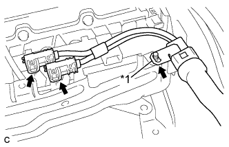 |
Disconnect the 2 connectors shown in the illustration.
| *1 | Shielded Wire Ground |
Disconnect the shielded wire ground and frame wire.
| 17. REMOVE HV BATTERY |
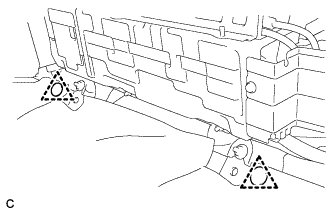 |
Remove the 2 clips.
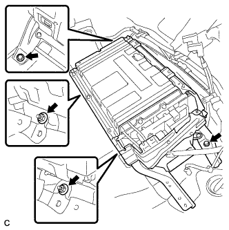 |
Remove the 2 bolts and 2 nuts.
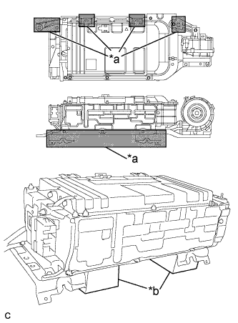 |
Remove the HV battery.
| *a | Area A |
| *b | Attachment |
| 18. REMOVE HYBRID BATTERY SERVICE PLUG COVER |
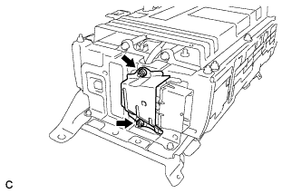 |
Remove the 2 nuts and hybrid battery service plug cover.
| 19. REMOVE NO. 1 HYBRID BATTERY SHIELD SUB-ASSEMBLY |
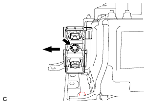 |
Remove the bolt and electric vehicle battery plug as shown in the illustration.
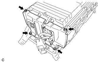 |
Remove the 2 bolts, 2 nuts and No. 1 hybrid shield sub-assembly.
| 20. REMOVE NO. 2 HYBRID VEHICLE BATTERY CARRIER BRACKET SUB-ASSEMBLY |
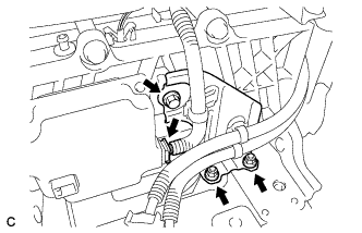 |
Disconnect the connector.
Remove the bolt and 2 nuts.
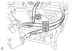 |
Disconnect the 3 clamps and remove the No. 2 hybrid vehicle battery carrier bracket sub-assembly.
| 21. REMOVE BATTERY SMART UNIT |
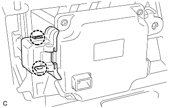 |
Disengage the 2 claws to remove the wiring harness protector cover from the battery smart unit connector.
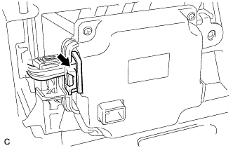 |
Disconnect the battery smart unit connector.
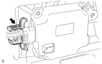 |
Remove the wiring harness protector from the battery smart unit connector.
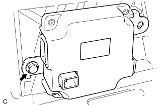 |
Remove the bolt and battery smart unit from the HV battery.
| 22. REMOVE NO. 2 HYBRID BATTERY SHIELD SUB-ASSEMBLY |
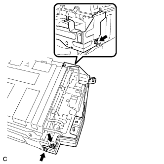 |
Remove the 2 bolts, nut and No. 2 hybrid battery shield sub-assembly.
| 23. REMOVE HYBRID BATTERY JUNCTION BLOCK ASSEMBLY |
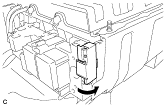 |
Open the terminal cover.
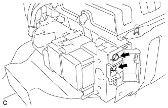 |
Using an insulated tool, remove the 2 bolts.
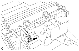 |
Disconnect the connector.
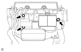 |
Remove the 3 bolts and hybrid battery junction block assembly.
| 24. REMOVE NO. 1 HYBRID BATTERY COVER INTAKE DUCT |
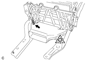 |
Disconnect the HV battery thermistor.
Remove the clip and No. 1 hybrid battery cover intake duct.
| 25. REMOVE UPPER HYBRID BATTERY COVER SUB-ASSEMBLY |
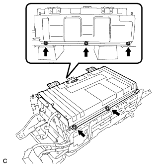 |
Remove the 5 nuts and upper hybrid battery cover sub-assembly.
| 26. DISCONNECT NO. 1 HYBRID BATTERY PACKING |
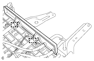 |
Disconnect the 2 clamps.
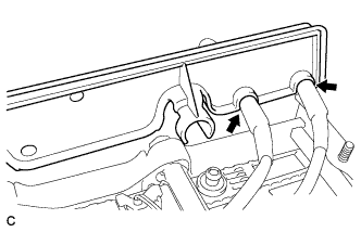 |
Disconnect the 2 wire harnesses and remove the No. 1 hybrid battery packing.