DTC P0A10-592 DC / DC Converter Status Circuit High Input |
| DTC No. | INF Code | DTC Detection Condition | Trouble Area |
| P0A10 | 592 | Short to +B in the DC/DC converter VLO signal line (1 trip detection logic) |
|
| 1.CHECK POWER MANAGEMENT CONTROL ECU (CHECK WAVEFORM) |
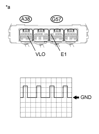
Connect an oscilloscope between the power management control ECU terminals specified in the table below.
Turn the ignition switch to ON (IG).
![]() |
Measure the waveform.
| Item | Content |
| Terminal | A38-11 (VLO) - G57-6 (E1) |
| Equipment Setting | 5 V/DIV., 50 ms/DIV. |
| Condition | Ignition switch ON (IG) |
| *a | Component with harness connected (Power Management Control ECU) |
Turn the ignition switch off.
|
| ||||
| OK | |
| 2.CLEAR DTC |
Connect the Techstream to the DLC3.
Turn the ignition switch to ON (IG).
Enter the following menus: Powertrain / Hybrid Control / Trouble Codes.
Read and record the DTCs and freeze frame data.
Clear DTCs and freeze frame data.
Turn the ignition switch off.
| NEXT | |
| 3.CHECK DTC OUTPUT (HYBRID CONTROL) |
Connect the Techstream to the DLC3.
Turn the ignition switch to ON (IG).
Enter the following menus: Powertrain / Hybrid Control / Trouble Codes.
Check if DTCs are output.
| Result | Proceed to |
| P0A10-592 is not output. | A |
| P0A10-592 is output again. | B |
Turn the ignition switch off.
|
| ||||
| A | ||
| ||
| 4.CHECK HARNESS AND CONNECTOR (INVERTER WITH CONVERTER ASSEMBLY - POWER MANAGEMENT CONTROL ECU) |
Check that the service plug grip is not installed.
Disconnect connector A38 from the power management control ECU.
Disconnect connector A47 from the inverter with converter assembly.
Connect the cable to the negative (-) auxiliary battery terminal.
Turn the ignition switch to ON (IG).
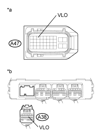
![]() |
Measure the voltage according to the value(s) in the table below.
| Tester Connection | Switch Condition | Specified Condition |
| A47-3 (VLO) or A38-11 (VLO) - Body ground | Ignition switch ON (IG) | Below 1 V |
| *a | Front view of wire harness connector (to Inverter with Converter Assembly) |
| *b | Rear view of wire harness connector (to Power Management Control ECU) |
Turn the ignition switch off.
Disconnect the cable from the negative (-) auxiliary battery terminal.
Connect the inverter with converter assembly connector.
Connect the power management control ECU connector.
|
| ||||
| OK | |
| 5.REPLACE POWER MANAGEMENT CONTROL ECU |
| NEXT | |
| 6.CLEAR DTC |
Connect the Techstream to the DLC3.
Turn the ignition switch to ON (IG).
Enter the following menus: Powertrain / Hybrid Control / Trouble Codes.
Read and record the DTCs and freeze frame data.
Clear DTCs and freeze frame data.
Turn the ignition switch off.
| NEXT | |
| 7.CHECK DTC OUTPUT (HYBRID CONTROL) |
Connect the Techstream to the DLC3.
Turn the ignition switch to ON (IG).
Enter the following menus: Powertrain / Hybrid Control / Trouble Codes.
Check if DTCs are output.
| Result | Proceed to |
| P0A10-592 is not output. | A |
| P0A10-592 is output again. | B |
Turn the ignition switch off.
|
| ||||
| A | ||
| ||