 |
Apply lithium soap base glycol grease to the push rod pin and installation hole of the brake pedal sub-assembly.
 | Lithium Soap Base Glycol Grease |
BRAKE PEDAL > INSTALLATION |
| 1. INSTALL BRAKE PEDAL SUPPORT ASSEMBLY |
Install the brake pedal support assembly with the 4 nuts.
Engage the wire harness clamp to the brake pedal support assembly.
Install the brake pedal support assembly to the instrument panel reinforcement assembly with the bolt.
Engage the wire harness clamp to the brake pedal support assembly.
| 2. INSTALL PUSH ROD PIN |
|
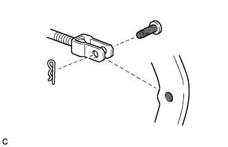
Apply lithium soap base glycol grease to the push rod pin and installation hole of the brake pedal sub-assembly.
| Lithium Soap Base Glycol Grease |
Install the push rod pin and a new clip to connect the push rod clevis to the brake pedal support assembly.
| 3. INSTALL BRAKE PEDAL RETURN SPRING |
Install the brake pedal return spring to the brake pedal support assembly and push rod pin.
| 4. CONNECT NO. 2 STEERING INTERMEDIATE SHAFT ASSEMBLY |
When reusing the electric power steering column sub-assembly and No. 2 steering intermediate shaft assembly:
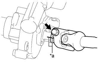 |
Align the matchmarks on the No. 2 steering intermediate shaft assembly and the steering column assembly, and install them.
| *a | Matchmark |
When replacing the electric power steering column sub-assembly or No. 2 steering intermediate shaft assembly:
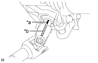 |
Align the marking (pink) on the steering column assembly shaft with the slit of the No. 2 steering intermediate shaft assembly, and install them.
| *a | Marking (Pink) |
| *b | Slit |
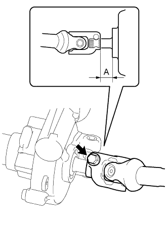 |
Install the bolt while aligning the No. 2 steering intermediate shaft assembly with the position A as shown in the illustration.
| 5. CONNECT STEERING SLIDING YOKE SUB-ASSEMBLY |
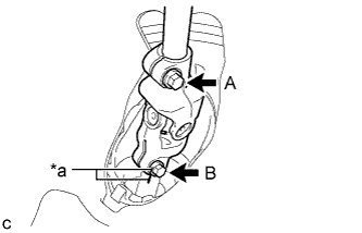 |
Install the steering sliding yoke sub-assembly to the steering gear assembly.
| *a | Matchmark |
Install bolt B.
Tighten bolt A.
| 6. INSTALL COLUMN HOLE COVER SILENCER SHEET |
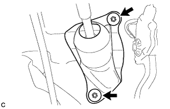 |
Install the column hole cover silencer sheet with the 2 clips.
Install the floor carpet.
| 7. INSTALL STOP LIGHT SWITCH MOUNTING ADJUSTER |
| 8. INSTALL STOP LIGHT SWITCH ASSEMBLY |
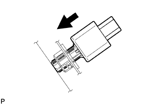 |
Insert the stop light switch assembly until the threaded sleeve hits the pedal.
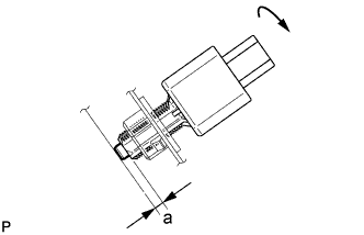 |
Make a quarter turn clockwise to install the stop light switch assembly.
Connect the connector.
Check the protrusion of the plunger.
| Area | Measurement |
| a | 0.5 to 2.6 mm (0.0197 to 0.102 in.) |
| 9. INSTALL BRAKE PEDAL STROKE SENSOR ASSEMBLY |
When installing a new brake pedal stroke sensor assembly:
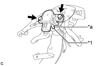 |
Install a new brake pedal stroke sensor assembly to the brake pedal support assembly with the 2 bolts.
| *1 | Brake Pedal Stroke Sensor Assembly Lever |
| *a | Brake Pedal Groove |
Connect the connector.
Firmly depress the brake pedal and break the brake pedal stroke sensor assembly lever set pin.
Remove the broken lever set pin.
When reusing the brake pedal stroke sensor assembly:
|
Install the brake pedal stroke sensor assembly to the brake pedal support assembly and temporarily tighten the 2 bolts.
| *1 | Brake Pedal Stroke Sensor Assembly Lever |
| *a | Brake Pedal Groove |
Connect the connector.
| 10. INSTALL INSTRUMENT CLUSTER FINISH PANEL SUB-ASSEMBLY |
| 11. CONNECT CABLE TO AUXILIARY BATTERY NEGATIVE TERMINAL |
| 12. INSPECT AND ADJUST BRAKE PEDAL |
| 13. PERFORM INITIALIZATION AND CALIBRATION OF LINEAR SOLENOID VALVE |