Home › Steering › POWER ASSIST SYSTEMS › POWER STEERING SYSTEM

DTC    C1553/53    When Resetting Voltage, Vehicle is Being Driven

for Preparation Click here


DESCRIPTION

If the power steering ECU assembly determines that the motor power source voltage and the IG voltage are not within the specified range, it stops the power assist as a fail-safe function.

DTC No.
DTC Detection Condition
Trouble Area
C1553/53
  1. PIG power source overvoltage
  2. IG power source overvoltage
  1. IG and PIG power source circuits
  2. Power steering ECU assembly

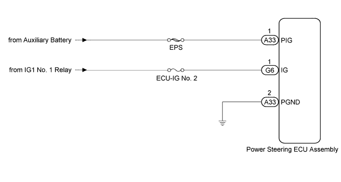
WIRING DIAGRAM


C210563E08


INSPECTION PROCEDURE

NOTICE:
If the power steering ECU assembly has been replaced with a new one, perform assist map writing and torque sensor zero point calibration (Click here).

1.CHECK HARNESS AND CONNECTOR (IG, PIG)
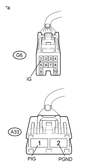
C250087E04
  1. Disconnect the connectors from the power steering ECU assembly.

  1. Measure the voltage according to the value(s) in the table below.

    Standard Voltage:
    Tester Connection
    Condition
    Specified Condition
    G6-1 (IG) - A33-2 (PGND)
    Ignition switch ON (IG)
    9 to 16 V
    A33-1 (PIG) - A33-2 (PGND)
    Always
    9 to 16 V

    Text in Illustration 
    *a
    Front view of wire harness connector
    (to Power Steering ECU Assembly)


NG
REPAIR OR REPLACE HARNESS OR CONNECTOR
OK

REPLACE POWER STEERING ECU ASSEMBLY (Click here)