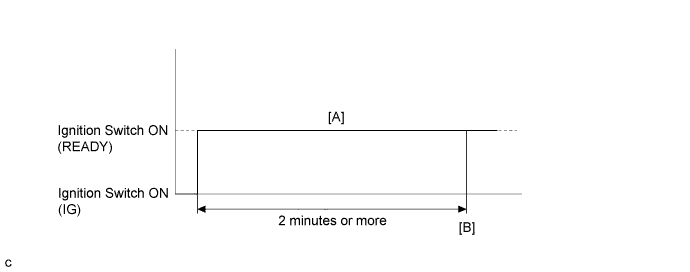
DTC P0C73-776 Motor Electronics Coolant Pump "A" Control Performance |
| DTC No. | INF Code | DTC Detection Condition | Trouble Area |
| P0C73 | 776 | The inverter water pump assembly revolution speed is abnormally high or low (or stop) for 1 minute or more. Or the inverter water pump assembly stops intermittently after abnormal revolution speed is detected. (1 trip detection logic) |
|
| DTC No. | Data List |
| P0C73-776 |
|
| DTC No. | Active Test |
| P0C73-776 | Activate the Water Pump*2 |
| Related DTCs | P0C73 (INF 776): Water pump malfunction |
| Required sensors / components | Inverter water pump assembly |
| Frequency of operation | Continuous |
| Duration | TMC's intellectual property |
| MIL operation | 1 driving cycle |
| Sequence of operation | None |
| The monitor will run whenever the following DTCs are not present | TMC's intellectual property |
| Other conditions belong to TMC's intellectual property | - |
| TMC's intellectual property | - |
| Power management control ECU | DTC P0C73 (INF 776) is not detected |
| 1.CHECK QUANTITY OF HV COOLANT |
Check the HV coolant level in the inverter reserve tank.
Check for HV coolant leaks.
| Result | Proceed to |
| No leaks are found and coolant level in the inverter reserve tank assembly is above the low line. | A |
| No leaks are found and coolant level in the inverter reserve tank assembly is below the low line. | B |
| HV coolant leaks are evident. | C |
|
| ||||
|
| ||||
| A | |
 |
| 2.CHECK COOLANT HOSE |
Check if the hoses of the cooling system are kinked or clogged.
|
| ||||
| OK | |
|
| 3.READ VALUE USING TECHSTREAM (INVERTER W/P REVOLUTION) |
Connect the Techstream to the DLC3.
Turn the ignition switch to ON (IG).
Enter the following menus: Powertrain / Hybrid Control / Data List / Inverter W/P Revolution.
Read the Data List.
| Tester Display | Switch Condition | Specified Condition |
| Inverter W/P Revolution | Ignition switch ON (IG) | 625 rpm or less |
Turn the ignition switch off.
|
| ||||
| OK | |
|
| 4.CLEAR DTC |
Connect the Techstream to the DLC3.
Turn the ignition switch to ON (IG).
Enter the following menus: Powertrain / Hybrid Control / Trouble Codes.
Clear DTCs and freeze frame data.
Turn the ignition switch off.
| NEXT | |
|
| 5.PERFORM ACTIVE TEST USING TECHSTREAM (ACTIVATE THE WATER PUMP) |
Connect the Techstream to the DLC3.
Turn the ignition switch to ON (IG).
Enter the following menus: Powertrain / Hybrid Control / Active Test / Activate the Water Pump.
Select Inverter W/P Revolution in the Data List.
While performing the "Activate the Water Pump" Active Test, check Inverter W/P Revolution in the Data List.
| Tester Display | Switch Condition | Specified Condition |
| Inverter W/P Revolution | Ignition switch ON (IG) | 2250 to 5625 rpm |
Turn the ignition switch off.
|
| ||||
| OK | |
|
| 6.CHECK HV COOLANT (CHECK FOR CONDITIONS THAT MAY HAVE CAUSED FREEZING) |
Connect the Techstream to the DLC3.
Turn the ignition switch to ON (IG).
Enter the following menus: Powertrain / Hybrid Control / Trouble Codes.
Read the freeze frame data Ambient Temperature using the Techstream.
Check if the freeze frame data Ambient Temperature is below freezing.
| Result | Proceed to |
| Ambient Temperature value is above freezing temperature of the HV coolant. | A |
| Ambient Temperature value is below freezing temperature of the HV coolant. | B |
Turn the ignition switch off.
|
| ||||
| A | ||
 | ||
| ||
| 7.CHECK CONNECTOR CONNECTION CONDITION (POWER MANAGEMENT CONTROL ECU CONNECTOR) |
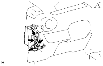 |
Check the connector connections and contact pressure of the relevant terminals for the power management control ECU connectors (Click here).
|
| ||||
| OK | |
|
| 8.CHECK CONNECTOR CONNECTION CONDITION (INVERTER WATER PUMP ASSEMBLY CONNECTOR) |
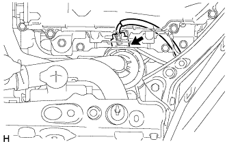 |
Check the connector connections and contact pressure of the relevant terminals for the inverter water pump assembly connector (Click here).
|
| ||||
| OK | |
|
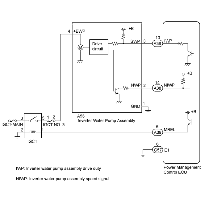
| 9.CHECK HARNESS AND CONNECTOR (POWER MANAGEMENT CONTROL ECU - INVERTER WATER PUMP ASSEMBLY) |
Disconnect connector A38 from the power management control ECU.
Disconnect connector A53 from the inverter water pump assembly.
Measure the resistance according to the value(s) in the table below.
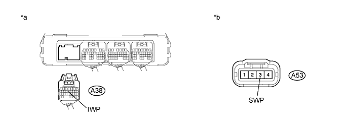
| *a | Rear view of wire harness connector (to Power Management Control ECU) | *b | Front view of wire harness connector (to Inverter Water Pump Assembly) |
| Tester Connection | Switch Condition | Specified Condition |
| A53-3 (SWP) - A38-13 (IWP) | Ignition switch off | Below 1 Ω |
| Tester Connection | Switch Condition | Specified Condition |
| A53-3 (SWP) or A38-13 (IWP) - Body ground and other terminals | Ignition switch off | 10 kΩ or higher |
Connect the power management control ECU connector.
Connect the inverter water pump assembly connector.
|
| ||||
| OK | |
|
| 10.READ VALUE USING TECHSTREAM (INVERTER W/P REVOLUTION) |
Connect the Techstream to the DLC3.
Turn the ignition switch to ON (IG).
Enter the following menus: Powertrain / Hybrid Control / ECU Data List / Inverter W/P Revolution.
Disconnect connector A53 from the inverter water pump assembly.
Read the Data List.
| Tester Display | Switch Condition | Specified Condition |
| Inverter W/P Revolution | Ignition switch ON (IG) | 125 rpm or less |
Turn the ignition switch off.
Connect the inverter water pump assembly connector.
|
| ||||
| OK | |
|
| 11.CHECK HARNESS AND CONNECTOR (POWER MANAGEMENT CONTROL ECU - INVERTER WATER PUMP ASSEMBLY) |
Disconnect connector A38 from the power management control ECU.
Turn the ignition switch to ON (IG).
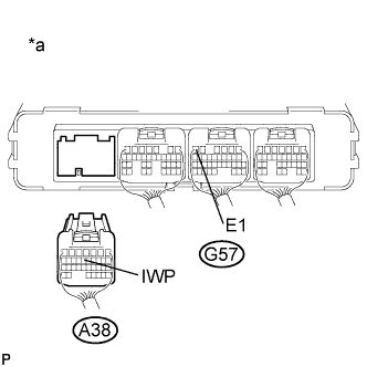 |
Measure the voltage according to the value(s) in the table below.
| Tester Connection | Switch Condition | Specified Condition |
| A38-13 (IWP) - G57-6 (E1) | Ignition switch ON (IG) | 11 to 14 V |
| *a | Rear view of wire harness connector (to Power Management Control ECU) |
Turn the ignition switch off.
Connect the power management control ECU connector.
|
| ||||
| OK | |
|
| 12.CHECK POWER MANAGEMENT CONTROL ECU (CHECK WAVEFORM) |
Turn the ignition switch to ON (IG).
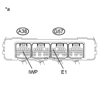 |
While turning the ignition switch to ON (IG), check the waveform between the power management control ECU terminals.
| Item | Content |
| Terminal | A38-13 (IWP) - G57-6 (E1) |
| Equipment Setting | 5 V/DIV., 50 ms./DIV. |
| Condition | Ignition switch ON (IG) |
| *a | Component with Harness Connected (Power Management Control ECU) |
Turn the ignition switch off.
|
| ||||
| OK | ||
| ||
| ||

