 |
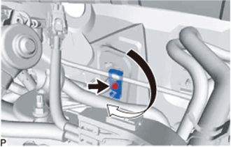
Rotate the hook connector in the direction indicated by the arrow in the illustration.
COOLER EXPANSION VALVE > INSTALLATION |
| 1. INSTALL COOLER EXPANSION VALVE |
Apply sufficient compressor oil to 2 new O-rings and the fitting surfaces of the cooler expansion valve.
Install the 2 O-rings onto the No. 1 cooler evaporator sub-assembly.
Using a 4 mm hexagon wrench, install a new cooler expansion valve with the 2 hexagon bolts.
| 2. CONNECT LIQUID PIPE SUB-ASSEMBLY |
Remove the vinyl tape from the liquid pipe sub-assembly.
Sufficiently apply compressor oil to a new O-ring and fitting surface of the liquid pipe sub-assembly.
Install the O-ring to the liquid pipe sub-assembly.
Install the liquid pipe sub-assembly.
| 3. CONNECT SUCTION PIPE SUB-ASSEMBLY |
Remove the vinyl tape from the pipe.
Sufficiently apply compressor oil to a new O-ring and the fitting surface of the suction pipe sub-assembly.
Install the O-ring onto the suction pipe sub-assembly.
Connect the suction pipe sub-assembly.
|
Rotate the hook connector in the direction indicated by the arrow in the illustration.
Insert the pipe joint into the fitting hole securely and tighten a new bolt.
| 4. INSTALL OUTER COWL TOP PANEL SUB-ASSEMBLY |
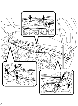 |
Install the outer cowl top panel sub-assembly with the 8 bolts and nut.
Engage the clamp to install the wire harness.
| 5. INSTALL FRONT NO. 1 VENTILATOR SEAL |
Engage the clamp to install the front No. 1 ventilator seal to the outer cowl top panel sub-assembly.
| 6. INSTALL FRONT AIR SHUTTER SEAL |
Engage the clamp to install the front air shutter seal to the outer cowl top panel sub-assembly.
| 7. INSTALL INNER COWL TOP TO COWL BRACE |
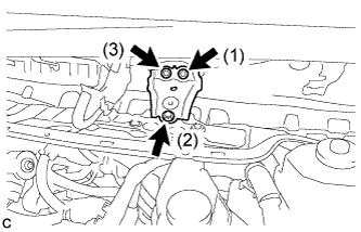 |
Install the inner cowl top to cowl brace to the outer cowl top panel sub-assembly with the 3 bolts.
| 8. INSTALL WINDSHIELD WIPER MOTOR AND LINK ASSEMBLY |
| 9. CHARGE AIR CONDITIONING SYSTEM WITH REFRIGERANT |
Perform vacuum purging using a vacuum pump or appropriate equipment.
Charge the air conditioning system with refrigerant.
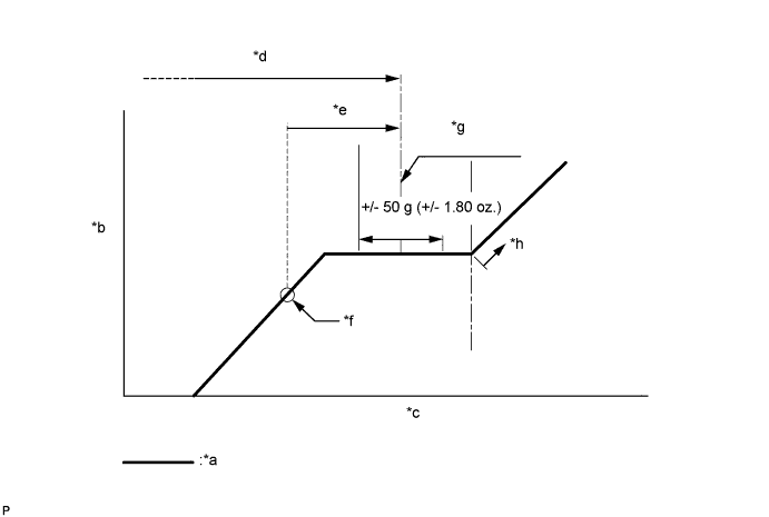
| *a | Sub-cool System | *b | High Pressure |
| *c | Refrigerant Amount | *d | Standard charge amount |
| *e | Charge additional 100g (3.5 oz.) | *f | Point where bubbles disappear |
| *g | Mean value in proper range | *h | Overcharged |
| 10. WARM UP COMPRESSOR |
Keep the A/C switch on for at least 2 minutes to warm up the compressor.
| 11. INSPECT FOR REFRIGERANT LEAK |
After recharging the air conditioning system with refrigerant, inspect for refrigerant leaks using a halogen leak detector.
Carry out the test under the following conditions:
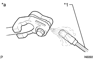 |
Using a halogen leak detector, inspect for refrigerant leaks from the air conditioning system.
| *1 | Halogen Leak Detector |
| *a | Inspect for Leak |
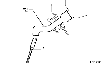 |
Bring the halogen leak detector close to the drain hose with the detector power off, and then turn the detector on.
| *1 | Halogen Leak Detector |
| *2 | Drain Hose |
If a refrigerant leak is not detected from the drain hose, remove the blower motor control from the cooling unit. Insert the halogen leak detector sensor into the unit and check for a leak.
Disconnect the pressure sensor connector and leave it for approximately 20 minutes. Bring the halogen leak detector close to the pressure sensor and check for a leak.