When using a new instrument panel sub-assembly:
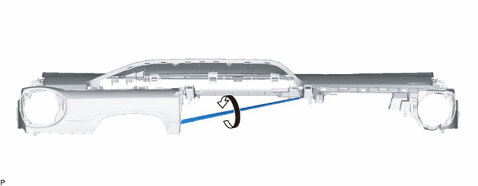
Immediately before installing the upper instrument panel assembly, twist and cut off the portion shown in the illustration.
UPPER INSTRUMENT PANEL > INSTALLATION |
| 1. INSTALL UPPER INSTRUMENT PANEL ASSEMBLY |
When using a new instrument panel sub-assembly:
Immediately before installing the upper instrument panel assembly, twist and cut off the portion shown in the illustration.
Push the upper instrument panel assembly in the direction indicated by the arrow (1) to engage the 5 guides.
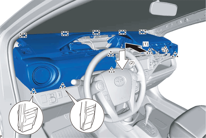
Push the upper instrument panel assembly in the direction indicated by the arrow (2) to engage the 7 clips to install the upper instrument panel assembly.
Install the screw <C>.
Install the bolt <A>.
Install the 2 clips.
w/ Navigation System:
Connect the connector.
| 2. CONNECT NO. 2 INSTRUMENT PANEL WIRE |
Check that the ignition switch is off.
Check that the cable is disconnected from the negative (-) auxiliary battery terminal.
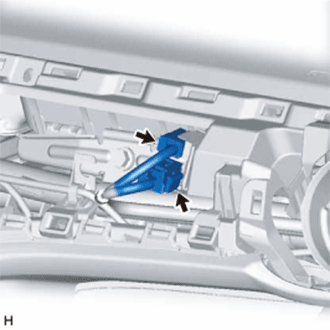 |
Connect the 2 connectors.
| 3. INSTALL FRONT PILLAR GARNISH RH |
| 4. INSTALL FRONT DOOR OPENING TRIM WEATHERSTRIP RH |
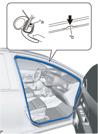 |
Align the alignment mark (Yellow green) on the weatherstrip with the protruding portion on the body indicated by the arrow in the illustration, and install the front door opening trim weatherstrip RH.
| *a | Alignment Mark (Yellow green) |
| *b | Flange Position |
| 5. INSTALL FRONT PILLAR GARNISH LH |
Remove the protective cover.
Make sure that the front pillar garnish clip is not damaged.
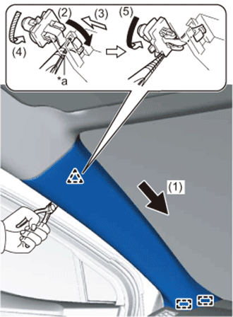 |
Push the front pillar garnish LH in the direction indicated by the arrow (1) shown in the illustration to engage the 2 guides.
| *a | Protective Tape |
Using needle-nose pliers with the tips wrapped with protective tape, bend the end of the front pillar garnish clip in the direction indicated by the arrow (2) shown in the illustration.
Push the front pillar garnish LH in the direction indicated by the arrow (3) shown in the illustration and insert it to the front pillar garnish clip.
Using needle-nose pliers with the tips wrapped with protective tape, rotate the front pillar garnish clip in the direction indicated by the arrow (4) shown in the illustration.
Using needle-nose pliers with the tips wrapped with protective tape, push the front pillar garnish clip in the direction indicated by the arrow (5) and rotate it to the position shown in the illustration.
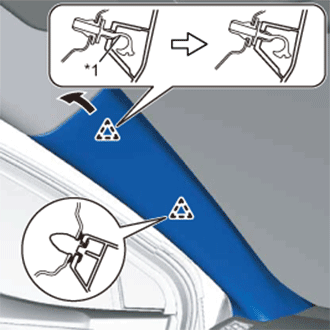 |
Engage the clip and front pillar garnish clip to install the front pillar garnish LH.
| *1 | Front Pillar Garnish Clip |
| 6. INSTALL FRONT DOOR OPENING TRIM WEATHERSTRIP LH |
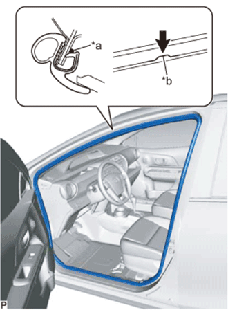 |
Align the alignment mark (Yellow) on the weatherstrip with the protruding portion on the body indicated by the arrow in the illustration, and install the front door opening trim weatherstrip LH.
| *a | Alignment Mark (Yellow) |
| *b | Flange Position |
| 7. INSTALL COMBINATION METER ASSEMBLY |
Engage the clamp.
Connect the 2 connectors.
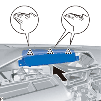 |
Engage the 3 clips.
Install the combination meter assembly with the 2 screws.
| 8. INSTALL INSTRUMENT CLUSTER FINISH PANEL SUB-ASSEMBLY |
Engage the 9 guides and 4 claws.
Install the instrument cluster finish panel sub-assembly with the 2 clips.
| 9. INSTALL CENTER INSTRUMENT PANEL REGISTER ASSEMBLY |
Engage the claw and 4 clips, to install the center instrument panel register assembly.
| 10. INSTALL INSTRUMENT CLUSTER FINISH PANEL GARNISH |
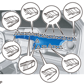 |
Engage the 10 guides and 12 clips to install the instrument cluster finish panel garnish.
| 11. INSTALL NO. 2 INSTRUMENT PANEL REGISTER ASSEMBLY |
Engage the 3 clips to install the No. 2 instrument panel register assembly.
| 12. INSTALL CENTER INSTRUMENT CLUSTER FINISH PANEL SUB-ASSEMBLY |
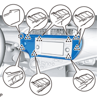 |
Engage the claw and 8 clips to install the center instrument cluster finish panel sub-assembly.
| 13. CONNECT CABLE TO AUXILIARY BATTERY NEGATIVE TERMINAL |
| 14. INSTALL FRONT FLOOR COVER RH |
Engage the 3 guides.
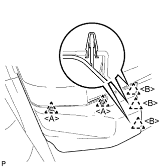 |
Engage the 3 clips <B> to install the front floor cover RH.
Install the 2 clips <A>.
| 15. INSPECT SRS WARNING LIGHT |