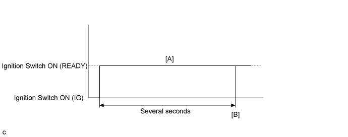
DTC P0560-117 System Voltage |
| DTC No. | INF Code | DTC Detection Condition | Trouble Area |
| P0560 | 117 | Malfunction in the power management control ECU back-up power source circuit (1 trip detection logic) |
|
| DTC No. | Data List |
| P0560-117 | +B |
| Related DTCs | P0560 (INF 117): System Voltage |
| Required sensors / components | Main: Back-up power source circuit Sub: Power management control ECU |
| Frequency of operation | Continuous |
| Duration | TMC's intellectual property |
| MIL operation | Immediately |
| Sequence of operation | None |
| The monitor will run whenever the following DTC is not present | TMC's intellectual property |
| Other conditions belong to TMC's intellectual property | - |
| TMC's intellectual property | - |
| Auxiliary battery voltage | Between 9 and 14 V |
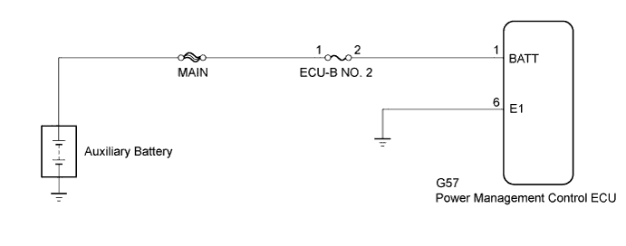
| 1.CHECK CONNECTOR CONNECTION CONDITION (POWER MANAGEMENT CONTROL ECU CONNECTOR) |
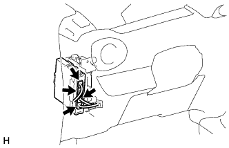 |
Check the connector connections and contact pressure of the relevant terminals for the power management control ECU connectors (Click here).
|
| ||||
| OK | |
 |
| 2.CHECK AUXILIARY BATTERY TERMINAL (CONTACT PROBLEM) |
Check the connection of the auxiliary battery terminal.
|
| ||||
| OK | |
|
| 3.INSPECT AUXILIARY BATTERY |
|
| ||||
| OK | |
|
| 4.CHECK FUSE (ECU-B NO. 2) |
Remove the ECU-B NO. 2 fuse from the No. 2 engine room relay block and No. 2 junction block assembly.
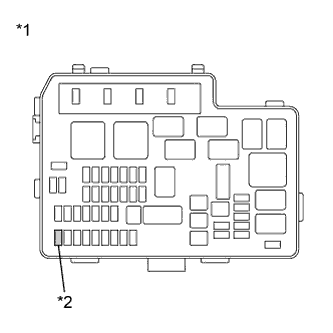 |
Measure the resistance according to the value(s) in the table below.
| Tester Connection | Switch Condition | Specified Condition |
| ECU-B NO. 2 fuse | Ignition switch off | Below 1 Ω |
| *1 | No. 2 Engine Room Relay Block and No. 2 Junction Block Assembly |
| *2 | ECU-B NO. 2 Fuse |
Install the ECU-B NO. 2 fuse.
|
| ||||
| OK | |
|
| 5.CHECK HARNESS AND CONNECTOR (POWER MANAGEMENT CONTROL ECU - ECU-B NO. 2 FUSE) |
Remove the ECU-B NO. 2 fuse from the No. 2 engine room relay block and No. 2 junction block assembly.
Disconnect connector G57 from the power management control ECU.
Measure the resistance according to the value(s) in the table below.
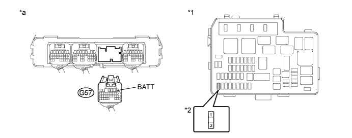
| *1 | No. 2 Engine Room Relay Block and No. 2 Junction Block Assembly | *2 | ECU-B NO. 2 Fuse |
| *a | Rear view of wire harness connector (to Power Management Control ECU) | - | - |
| Tester Connection | Switch Condition | Specified Condition |
| G57-1 (BATT) - 2 (ECU-B NO. 2 fuse) | Ignition switch off | Below 1 Ω |
| Tester Connection | Switch Condition | Specified Condition |
| G57-1 (BATT) or 2 (ECU-B NO. 2 fuse) - Body ground and other terminals | Ignition switch off | 10 kΩ or more |
Install the ECU-B NO. 2 fuse.
Connect the power management control ECU connector.
|
| ||||
| OK | |
|
| 6.CHECK HARNESS AND CONNECTOR (ECU-B NO. 2 FUSE - AUXILIARY BATTERY POSITIVE TERMINAL) |
Remove the ECU-B NO. 2 fuse from the No. 2 engine room relay block and No. 2 junction block assembly.
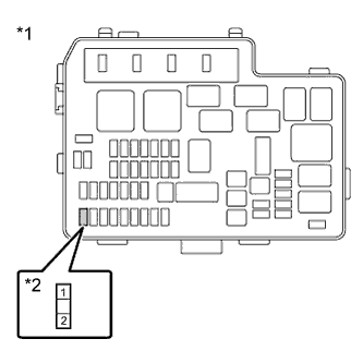 |
Measure the voltage according to the value(s) in the table below.
| Tester Connection | Switch Condition | Specified Condition |
| 1 (ECU-B NO. 2 fuse) - Body ground | Always | 11 to 14 V |
| *1 | No. 2 Engine Room Relay Block and No. 2 Junction Block Assembly |
| *2 | ECU-B NO. 2 Fuse |
Install the ECU-B NO. 2 fuse.
|
| ||||
| OK | |
|
| 7.RECONFIRM DTC OUTPUT (HYBRID CONTROL) |
Connect the Techstream to the DLC3.
Turn the ignition switch to ON (IG).
Enter the following menus: Powertrain / Hybrid Control / Trouble Codes.
Recheck for DTCs.
| Result | Proceed to |
| DTC P0560-117 is output again | A |
| DTC P0560-117 is not output | B |
|
| ||||
| A | ||
 | ||
| ||
