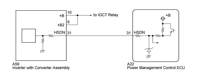
DTC P3232-749 Short to GND in Blocking of HV Gate Connection |
| DTC No. | INF Code | DTC Detection Condition | Trouble Area |
| P3232 | 749 | Short to GND in the emergency shutdown signal line while the IGBTs are being shut down. |
|
| 1.CHECK HARNESS AND CONNECTOR (POWER MANAGEMENT CONTROL ECU - INVERTER WITH CONVERTER) |
Check that the service plug grip is not installed.
Disconnect connector A59 from the inverter with converter assembly.
Disconnect connector A22 from the power management control ECU.
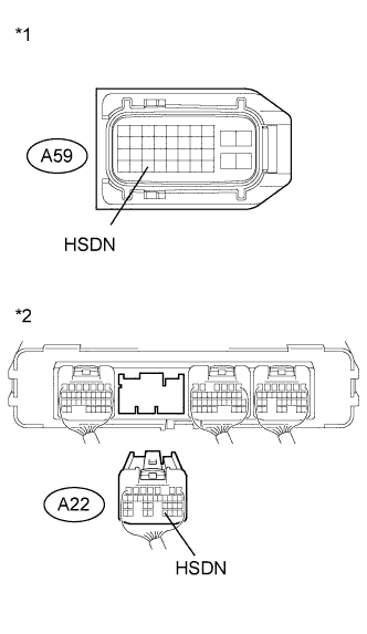 |
Measure the resistance according to the value(s) in the table below.
| Tester Connection | Switch Condition | Specified Condition |
| A22-31 (HSDN) or A59-31 (HSDN) - Body ground and other terminals | Power switch off | 10 kΩ or higher |
| *1 | Front view of wire harness connector (to Inverter with Converter Assembly) |
| *2 | Rear view of wire harness connector (to Power Management Control ECU) |
Connect the power management control ECU connector.
Connect the inverter with converter assembly connector.
|
| ||||
| OK | |
 |
| 2.CHECK INVERTER WITH CONVERTER ASSEMBLY |
Check that the service plug grip is not installed.
Disconnect connector A59 from the inverter with converter assembly.
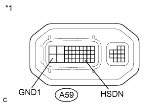 |
Measure the resistance according to the value(s) in the table below.
| Tester Connection | Switch Condition | Specified Condition |
| A59-31 (HSDN) - A59-28 (GND1) | Power switch off | 2.65 to 3.55 kΩ |
| *1 | Component without harness connected (Inverter with Converter Assembly) |
Connect the inverter with converter assembly connector.
|
| ||||
| OK | ||
 | ||
| ||
