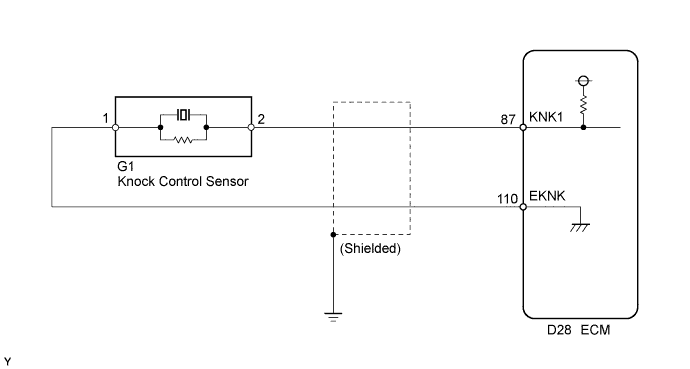
DTC P0327 Knock Sensor 1 Circuit Low Input (Bank 1 or Single Sensor) |
DTC P0328 Knock Sensor 1 Circuit High Input (Bank 1 or Single Sensor) |
| DTC No. | DTC Detection Condition | Trouble Area |
| P0327 | Output voltage of knock control sensor less than 0.5 V for 1 second or more (1 trip detection logic) |
|
| P0328 | Output voltage of knock control sensor more than 4.5 V for 1 second or more (1 trip detection logic) |
|
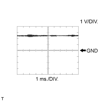
| ECM Terminal Name | Between KNK1 and EKNK |
| Tester Range | 1 V/DIV., 1 ms./DIV. |
| Condition | Engine speed maintained at 2500 rpm after warming up engine |
| 1.READ VALUE USING INTELLIGENT TESTER (KNOCK FEEDBACK VALUE) |
Connect the intelligent tester to the DLC3.
Turn the power switch on (IG) and turn the tester on.
Put the engine in inspection mode (maintenance mode) (Click here).
Start the engine.
Warm up the engine.
Enter the following menus: Powertrain / Engine and ECT / Data List / All Data / Knock Feedback Value.
Read the value while driving the vehicle.
| Malfunction does not occur | Knock Feedback Value changes |
| Malfunctions occur | Knock Feedback Value does not change |
|
| ||||
| OK | ||
 | ||
| ||
| 2.CHECK TERMINAL VOLTAGE (POWER SOURCE OF KNOCK CONTROL SENSOR) |
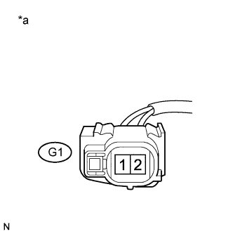 |
Disconnect the knock control sensor connector.
Turn the power switch on (IG).
Measure the voltage according to the value(s) in the table below.
| Tester Connection | Switch Condition | Specified Condition |
| G1-2 - G1-1 | Power switch on (IG) | 4.5 to 5.5 V |
| *a | Front view of wire harness connector (to Knock Control Sensor) |
Reconnect the knock control sensor connector.
|
| ||||
| OK | |
 |
| 3.INSPECT KNOCK CONTROL SENSOR |
Inspect the knock control sensor (Click here).
|
| ||||
| OK | ||
| ||
| ||
| 4.CHECK HARNESS AND CONNECTOR (KNOCK CONTROL SENSOR - ECM) |
Disconnect the knock control sensor connector.
Disconnect the ECM connector.
Measure the resistance according to the value(s) in the table below.
| Tester Connection | Condition | Specified Condition |
| G1-2 - D28-87 (KNK1) | Always | Below 1 Ω |
| G1-1 - D28-110 (EKNK) | Always | Below 1 Ω |
| Tester Connection | Condition | Specified Condition |
| G1-2 or D28-87 (KNK1) - Body ground | Always | 10 kΩ or higher |
| G1-1 or D28-110 (EKNK) - Body ground | Always | 10 kΩ or higher |
Reconnect the knock control sensor connector.
Reconnect the ECM connector.
|
| ||||
| OK | ||
| ||
| ||

