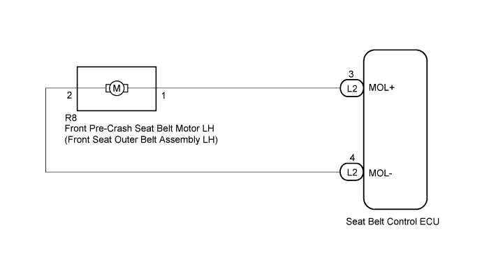
DTC B2005 Short to B+ in Seat Belt Motor LH Circuit |
| DTC No. | DTC Detection Condition | Trouble Area |
| B2005 | Short to B+ in the seat belt motor LH circuit continues for 1 second or more. |
|
| 1.INSPECT FRONT SEAT OUTER BELT ASSEMBLY LH |
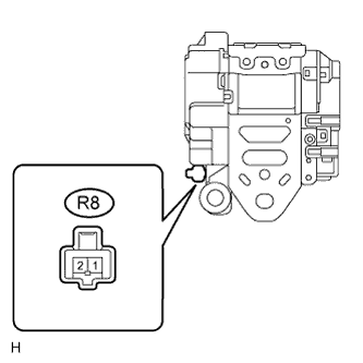 |
Disconnect the front seat outer belt assembly LH connector.
Turn the power switch on (IG).
Measure the voltage according to the value(s) in the table below.
| Tester Connection | Switch Condition | Specified Condition |
| R8-1 - Body ground | Power switch on (IG) | Below 1 V |
| R8-2 - Body ground | Power switch on (IG) | Below 1 V |
Reconnect the front seat outer belt assembly LH connector.
|
| ||||
| OK | |
 |
| 2.CHECK HARNESS AND CONNECTOR (FRONT SEAT OUTER BELT ASSEMBLY LH - SEAT BELT CONTROL ECU) |
Disconnect the cable from the negative (-) battery terminal.
Disconnect the front seat outer belt assembly LH connector.
Disconnect the seat belt control ECU connector.
Connect the cable to the negative (-) battery terminal.
Turn the power switch on (IG).
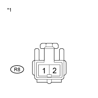 |
Measure the voltage according to the value(s) in the table below.
| Tester Connection | Switch Condition | Specified Condition |
| R8-1 - Body ground | Power switch on (IG) | Below 1 V |
| R8-2 - Body ground | Power switch on (IG) | Below 1 V |
| *1 | Front view of wire harness connector (to Front Seat Outer Belt Assembly LH) |
Disconnect the cable from the negative (-) battery terminal.
Reconnect the seat belt control ECU and front seat outer belt assembly LH connectors.
Connect the cable to the negative (-) battery terminal.
|
| ||||
| OK | ||
 | ||
| ||
