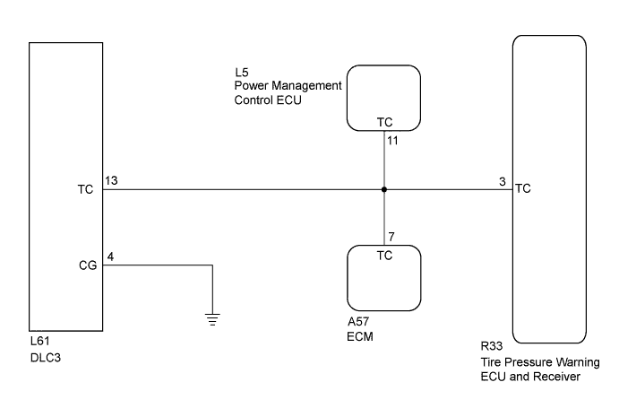
TIRE PRESSURE WARNING SYSTEM > TC and CG Terminal Circuit |
| 1.CHECK HARNESS AND CONNECTOR (TC of DLC3 - TIRE PRESSURE WARNING ECU AND RECEIVER, ECM AND POWER MANAGEMENT CONTROL ECU) |
Disconnect the R33 tire pressure warning ECU and receiver connector.
Disconnect the A57 ECM connector.
Disconnect the L5 power management control ECU connector.
Measure the resistance according to the value(s) in the table below.
| Tester Connection | Condition | Specified Condition |
| R33-3 (TC) - L61-13 (TC) | Always | Below 1 Ω |
| R33-3 (TC), A57-7 (TC), L5-11 (TC) or L61-13 (TC) - Body ground | Always | 10 kΩ or higher |
|
| ||||
| OK | |
 |
| 2.CHECK HARNESS AND CONNECTOR (CG of DLC3 - BODY GROUND) |
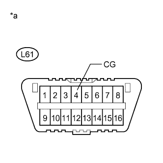 |
Measure the resistance according to the value(s) in the table below.
| Tester Connection | Condition | Specified Condition |
| L61-4 (CG) - Body ground | Always | Below 1 Ω |
| *a | Front view of DLC3 |
|
| ||||
| OK | ||
 | ||
| ||
