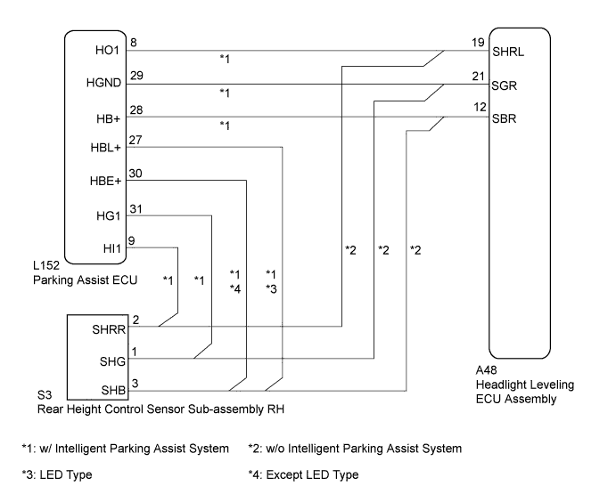
DTC B241A Rear Height Control Sensor |
| DTC No. | DTC Detecting Condition | Trouble Area |
| B241A |
|
|
| DTC No. | DTC Detecting Condition | Trouble Area |
| B241A |
|
|
| 1.CHECK FOR DTC |
Clear the DTCs (Click here).
Check for DTCs (Click here).
|
| ||||
| OK | ||
 | ||
| ||
| 2.CHECK VEHICLE CONDITION |
Check the vehicle condition.
| Result | Proceed to |
| w/o Intelligent Parking Assist System | A |
| w/ Intelligent Parking Assist System | B |
|
| ||||
| A | |
 |
| 3.READ VALUE USING INTELLIGENT TESTER |
Connect the intelligent tester to the DLC3.
Turn the power switch on (IG).
Turn the intelligent tester on.
Enter the following menus: Body / HL Auto Leveling / Data List.
Read the display on the intelligent tester.
| Tester Display | Measurement Item/Range | Normal Condition | Diagnostic Note |
| Height Sens Pw Supply Val | Rear height control sensor power supply value / 0 to 6.25 V | Approx. 5.0 V | - |
| Rr Height Sens Signal Val | Rear height control sensor signal value / 0 to 5 V | Approx. 2.5 V (When the vehicle is level) | Value is changed according to vehicle height |
|
| ||||
| OK | |
|
| 4.INSPECT REAR HEIGHT CONTROL SENSOR SUB-ASSEMBLY RH |
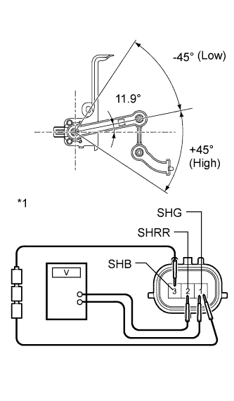 |
Connect 3 dry cell batteries (1.5 V) in series.
Remove the rear height control sensor sub-assembly RH (Click here).
Connect a positive (+) lead from the battery to terminal 3 (SHB) and a negative (-) lead from the battery to terminal 1 (SHG).
Measure the voltage between terminals 2 (SHRR) and 1 (SHG) while slowly moving the link up and down.
| Tester Connection | Condition | Specified Condition |
| 2 (SHRR) - 1 (SHG) | +45° (High) | 4.05 V |
| 0° (Normal) | 2.25 V | |
| -45° (Low) | 0.45 V |
| *1 | Component without harness connected (Rear Height Control Sensor Sub-assembly RH) |
|
| ||||
| OK | ||
| ||
| ||
| 5.CHECK HARNESS AND CONNECTOR (HEADLIGHT LEVELING ECU ASSEMBLY - HEIGHT CONTROL SENSOR) |
Disconnect the A48 headlight leveling ECU assembly connector.
Disconnect the S3 rear height control sensor sub-assembly RH connector.
Measure the resistance according to the value(s) in the table below.
| Tester Connection | Condition | Specified Condition |
| A48-12 (SBR) - S3-3 (SHB) | Always | Below 1 Ω |
| A48-19 (SHRL) - S3-2 (SHRR) | Always | Below 1 Ω |
| A48-21 (SGR) - S3-1 (SHG) | Always | Below 1 Ω |
| A48-12 (SBR) - Body ground | Always | 10 kΩ or higher |
| A48-19 (SHRL) - Body ground | Always | 10 kΩ or higher |
| A48-21 (SGR) - Body ground | Always | 10 kΩ or higher |
|
| ||||
| OK | |
|
| 6.INSPECT REAR HEIGHT CONTROL SENSOR SUB-ASSEMBLY RH |
|
Connect 3 dry cell batteries (1.5 V) in series.
Remove the rear height control sensor sub-assembly RH (Click here).
Connect a positive (+) lead from the battery to terminal 3 (SHB) and a negative (-) lead from the battery to terminal 1 (SHG).
Measure the voltage between terminals 2 (SHRR) and 1 (SHG) while slowly moving the link up and down.
| Tester Connection | Condition | Specified Condition |
| 2 (SHRR) - 1 (SHG) | +45° (High) | 4.05 V |
| 0° (Normal) | 2.25 V | |
| -45° (Low) | 0.45 V |
| *1 | Component without harness connected (Rear Height Control Sensor Sub-assembly RH) |
|
| ||||
| OK | ||
| ||
| ||
| 7.CHECK FOR DTC (INTELLIGENT PARKING ASSIST SYSTEM) |
Check for DTCs (Click here).
|
| ||||
| OK | |
|
| 8.READ VALUE USING INTELLIGENT TESTER |
Connect the intelligent tester to the DLC3.
Turn the power switch on (IG).
Turn the intelligent tester on.
Enter the following menus: Body / HL Auto Leveling / Data List.
Read the display on the intelligent tester.
| Tester Display | Measurement Item/Range | Normal Condition | Diagnostic Note |
| Height Sens Pw Supply Val | Rear height control sensor power supply value / 0 to 6.25 V | Approx. 5.0 V | - |
| Rr Height Sens Signal Val | Rear height control sensor signal value / 0 to 5 V | Approx. 2.5 V (When the vehicle is level) | Value is changed according to vehicle height |
|
| ||||
| OK | |
|
| 9.REPLACE PARKING ASSIST ECU |
Temporarily replace the parking assist ECU with a new or normally functioning one (Click here).
Check for DTCs (Click here).
|
| ||||
| OK | ||
| ||
| ||
| 10.CHECK HARNESS AND CONNECTOR (SUSPENSION CONTROL ECU - AFS ECU) |
Disconnect the A48 headlight leveling ECU assembly connector.
Disconnect the L152 parking assist ECU connector.
Measure the resistance according to the value(s) in the table below.
| Tester Connection | Condition | Specified Condition |
| A48-12 (SBR) - L152-27 (HBL+)*1 | Always | Below 1 Ω |
| A48-12 (SBR) - L152-30 (HBE+)*2 | Always | Below 1 Ω |
| A48-19 (SHRL) - L152-8 (HO1) | Always | Below 1 Ω |
| A48-21 (SGR) - L152-29 (HGND) | Always | Below 1 Ω |
| A48-12 (SBR) - Body ground | Always | 10 kΩ or higher |
| A48-19 (SHRL) - Body ground | Always | 10 kΩ or higher |
| A48-21 (SGR) - Body ground | Always | 10 kΩ or higher |
|
| ||||
| OK | |
|
| 11.REPLACE PARKING ASSIST ECU |
Temporarily replace the parking assist ECU with a new or normally functioning one (Click here).
Check for DTCs (Click here).
|
| ||||
| OK | ||
| ||
| ||

