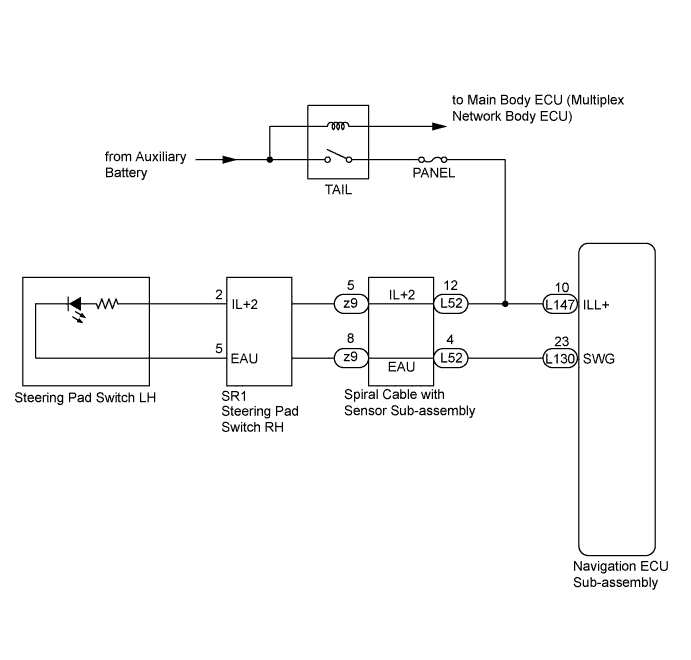
NAVIGATION SYSTEM (for Navigation Receiver Type) > Illumination Circuit |
| 1.CHECK ILLUMINATION |
Check if the illumination for the navigation ECU sub-assembly, steering pad switch assembly, heater control switch or others (hazard switch, transmission control switch, etc.) comes on when the light control switch is turned to the head or tail position.
| Result | Proceed to |
| Illumination comes on for all components except steering pad switch assembly. | A |
| Illumination comes on for all components except navigation ECU sub-assembly. | B |
| No illumination comes on (navigation ECU sub-assembly, hazard switch, heater control switch, etc.). | C |
|
| ||||
|
| ||||
| A | |
 |
| 2.CHECK HARNESS AND CONNECTOR (ILLUMINATION SIGNAL) |
Disconnect the spiral cable with sensor sub-assembly connector.
Measure the voltage according to the value(s) in the table below.
| Tester Connection | Condition | Specified Condition |
| L52-12 (IL+2) - Body ground | Power switch off Light control switch in the tail or head position | 11 to 14 V |
|
| ||||
| OK | |
|
| 3.INSPECT STEERING PAD SWITCH ASSEMBLY |
Disconnect the steering pad switch assembly connector.
Connect a auxiliary battery positive (+) lead to terminal IL+2 and a negative (-) lead to terminal EAU of the steering pad switch assembly connector.
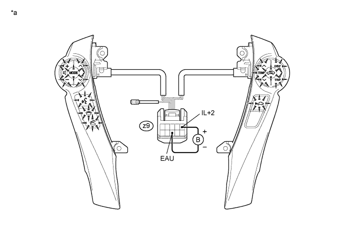
Check if the illumination for the steering pad switch assembly comes on.
| *a | Component without harness connected (Steering Pad Switch Assembly) | - | - |
Proceed to the next step based on the inspection result.
| Result | Proceed to |
| NG | A |
| OK | B |
|
| ||||
| A | |
|
| 4.INSPECT STEERING PAD SWITCH RH |
Disconnect the steering pad switch RH connectors.
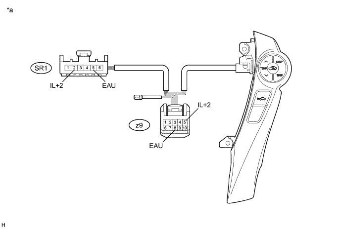
Measure the resistance according to the value(s) in the table below.
| Tester Connection | Condition | Specified Condition |
| SR1-2 (IL+2) - z9-5 (IL+2) | Always | Below 1 Ω |
| SR1-5 (EAU) - z9-8 (EAU) | Always | Below 1 Ω |
| *a | Component without harness connected (Steering Pad Switch RH) | - | - |
|
| ||||
| OK | ||
 | ||
| ||
| 5.INSPECT SPIRAL CABLE WITH SENSOR SUB-ASSEMBLY |
Disconnect the steering pad switch assembly connector.
Disconnect the spiral cable with sensor sub-assembly connector.
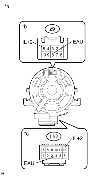 |
Measure the resistance according to the value(s) in the table below.
| Tester Connection | Condition | Specified Condition |
| z9-5 (IL+2) - L52-12 (IL+2) | Center | Below 1 Ω |
| 2.5 rotations to the left | ||
| 2.5 rotations to the right | ||
| z9-8 (EAU) - L52-4 (EAU) | Center | Below 1 Ω |
| 2.5 rotations to the left | ||
| 2.5 rotations to the right |
After setting the spiral cable with sensor sub-assembly to the center position, rotate the spiral cable with sensor sub-assembly 2.5 times clockwise. Then while rotating the spiral cable with sensor sub-assembly 5 times counterclockwise, measure the resistance as shown in the table below.
| Tester Connection | Condition | Specified Condition |
| z9-5 (IL+2) - L52-12 (IL+2) | Always | Below 1 Ω |
| z9-8 (EAU) - L52-4 (EAU) | Always | Below 1 Ω |
| *a | Component without harness connected (Spiral Cable with Sensor Sub-assembly) |
| *b | Steering Pad Switch Assembly Side |
| *c | Vehicle Side |
|
| ||||
| OK | |
|
| 6.CHECK HARNESS AND CONNECTOR (SPIRAL CABLE WITH SENSOR SUB-ASSEMBLY - NAVIGATION ECU SUB-ASSEMBLY) |
Disconnect the spiral cable with sensor sub-assembly connector.
Disconnect the navigation ECU sub-assembly connector.
Measure the resistance according to the value(s) in the table below.
| Tester Connection | Condition | Specified Condition |
| L52-4 (EAU) - L130-23 (SWG) | Always | Below 1 Ω |
|
| ||||
| OK | ||
| ||
| ||
| 7.CHECK HARNESS AND CONNECTOR (ILLUMINATION SIGNAL) |
Disconnect the navigation ECU sub-assembly connector.
Measure the voltage according to the value(s) in the table below.
| Tester Connection | Condition | Specified Condition |
| L147-10 (ILL+) - Body ground | Power switch off Light control switch in the tail or head position | 11 to 14 V |
|
| ||||
| OK | ||
| ||
| ||

