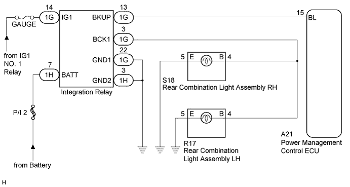
LIGHTING SYSTEM > Back-up Light Circuit |
| 1.CHECK HARNESS AND CONNECTOR (INTEGRATION RELAY - BATTERY AND BODY GROUND) |
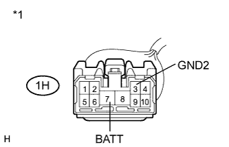 |
Disconnect the 1H integration relay connector.
Measure the voltage and resistance according to the value(s) in the table below.
| Tester Connector | Condition | Specified Condition |
| 1H-7 (BATT) - Body ground | Always | 11 to 14 V |
| Tester Connection | Condition | Specified Condition |
| 1H-3 (GND2) - Body ground | Always | Below 1 Ω |
| *1 | Front view of wire harness connector (to Integration Relay) |
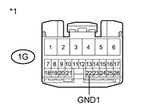 |
Disconnect the 1G integration relay connector.
Measure the resistance according to the value(s) in the table below.
| Tester Connection | Condition | Specified Condition |
| 1G-22 (GND1) - Body ground | Always | Below 1 Ω |
| *1 | Front view of wire harness connector (to Integration Relay) |
|
| ||||
| OK | |
 |
| 2.CHECK HARNESS AND CONNECTOR (INTEGRATION RELAY - POWER MANAGEMENT CONTROL ECU) |
Reconnect the A21 power management control ECU connector.
Disconnect the 1G integration relay connector.
Disconnect the A21 power management control ECU connector.
Measure the resistance according to the value(s) in the table below.
| Tester Connection | Condition | Specified Condition |
| 1G-13 (BKUP) - A21-15 (BL) | Always | Below 1 Ω |
| 1G-13 (BKUP) - Body ground | Always | 10 kΩ or higher |
|
| ||||
| OK | |
|
| 3.CHECK HARNESS OR CONNECTOR (INTEGRATION RELAY - REAR COMBINATION LIGHT ASSEMBLY) |
Disconnect the 1G integration relay connector.
Disconnect the S18 or R17 rear combination light assembly connector.
Measure the resistance according to the value(s) in the table below.
| Tester Connection | Condition | Specified Condition |
| 1G-3 (BCK1) - S18-4 (B) | Always | Below 1 Ω |
| 1G-3 (BCK1) - R17-4 (B) | Always | Below 1 Ω |
| 1G-3 (BCK1) - Body ground | Always | 10 kΩ or higher |
|
| ||||
| OK | |
|
| 4.REPLACE INTEGRATION NO.1 RELAY |
Temporarily replace the integration relay with a new or normally functioning one (Click here).
Check that the back-up lights operate normally.
|
| ||||
| OK | ||
 | ||
| ||
