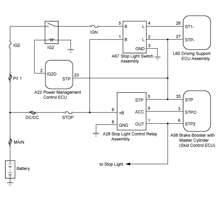
DTC C1A05 Stop Light Switch Circuit |
| DTC No. | DTC Detection Condition | Trouble Area |
| C1A05 | Voltages of terminals ST1- and STP- of driving support ECU are both below 1 V for 1 second |
|
| 1.CHECK HARNESS AND CONNECTOR (STOP LIGHT SWITCH ASSEMBLY - POWER SOURCE) |
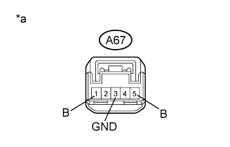 |
Measure the voltage and resistance according to the value(s) in the table below.
| Tester Connection | Condition | Specified Condition |
| A67-1 (B) - A67-3 (GND) | Power switch off | 11 to 14 V |
| A67-5 (B) - A67-3 (GND) | Power switch on (IG) | 11 to 14 V |
| Tester Connection | Condition | Specified Condition |
| A67-3 (GND) - Body ground | Always | Below 1 Ω |
| *a | Front view of wire harness connector (to Stop Light Switch Assembly) |
|
| ||||
| OK | |
 |
| 2.INSPECT STOP LIGHT SWITCH ASSEMBLY |
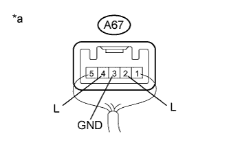 |
Remove the stop light switch assembly (Click here).
Measure the voltage according to the value(s) in the table below.
| Tester Connection | Switch Condition | Specified Condition |
| A67-2 (L) - A67-3 (GND) | Power switch off, brake pedal not depressed | Below 1 V |
| A67-4 (L) - A67-3 (GND) | 11 to 14 V | |
| A67-2 (L) - A67-3 (GND) | Power switch off, brake pedal depressed | 11 to 14 V |
| A67-4 (L) - A67-3 (GND) | Below 1 V |
| *a | Component with harness connected (Stop Light Switch Assembly) |
|
| ||||
| OK | |
|
| 3.CHECK HARNESS AND CONNECTOR (STOP LIGHT SWITCH ASSEMBLY - DRIVING SUPPORT ECU) |
Disconnect the stop light switch assembly connector.
Disconnect the driving support ECU connector.
Measure the resistance according to the value(s) in the table below.
| Tester Connection | Switch Condition | Specified Condition |
| A67-4 (L) - L60-28 (ST1-) | Always | Below 1 Ω |
| A67-2 (L) - L60-27 (STP-) | Always | Below 1 Ω |
| Tester Connection | Switch Condition | Specified Condition |
| A67-4 (L) or L60-28 (ST1-) - Body ground | Always | 10 kΩ or higher |
| A67-2 (L) or L60-27 (STP-) - Body ground | Always | 10 kΩ or higher |
|
| ||||
| OK | |
|
| 4.CHECK HARNESS AND CONNECTOR (STOP LIGHT CONTROL RELAY - BODY GROUND) |
Disconnect the stop light control relay assembly connector.
Measure the resistance according to the value(s) in the table below.
| Tester Connection | Condition | Specified Condition |
| A67-2 (L) - Body ground | Always | 10 kΩ or higher |
| A67-4 (L) - Body ground | Always | 10 kΩ or higher |
|
| ||||
| OK | ||
 | ||
| ||
