 |
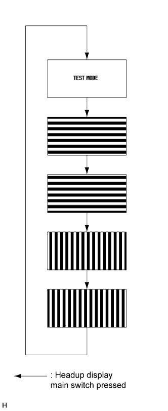
Inspect the headup display (combination meter mirror ECU) as shown in the illustration.
METER / GAUGE SYSTEM > ON-VEHICLE INSPECTION |
| 1. INSPECT SPEEDOMETER |
Check speedometer operation.
Before starting the following inspection, check if the Brake Control System outputs the DTCs.
Check the values by referring to the table below.
| Tester Display | Measurement Item/Range | Normal Condition | Diagnostic Note |
| Vehicle Speed | Vehicle speed/Min.: 0 km/h (0 mph), Max.: 326 km/h (203 mph) | Vehicle stop: 0 km/h (0 mph) | - |
| Intelligent Tester Indication (km/h) | Acceptable Range (km/h) |
| 20 | 21.0 to 25.0 |
| 40 | 42.0 to 46.0 |
| 60 | 63.0 to 67.0 |
| 80 | 84.0 to 88.0 |
| 100 | 104.0 to 109.0 |
| 120 | 125.0 to 130.0 |
| 140 | 146.0 to 151.0 |
| 160 | 167.0 to 173.0 |
| 180 | 187.0 to 194.0 |
| Intelligent Tester Indication (mph) | Acceptable Range (mph) |
| 20 | 21.0 to 23.0 |
| 40 | 42.0 to 44.0 |
| 60 | 63.0 to 66.0 |
| 80 | 83.0 to 87.0 |
| 100 | 104.0 to 108.0 |
| 120 | 125.0 to 129.0 |
| 140 | 146.0 to 150.0 |
| Intelligent Tester Indication (km/h) | Acceptable Range (km/h) |
| 20 | 21.0 to 23.6 |
| 40 | 41.0 to 44.7 |
| 60 | 61.0 to 65.2 |
| 80 | 81.0 to 86.3 |
| 100 | 102.0 to 105.9 |
| 120 | 122.0 to 126.5 |
| 140 | 142.0 to 147.1 |
| 160 | 162.0 to 167.7 |
| 180 | 183.0 to 187.2 |
| 2. INSPECT HEADUP DISPLAY (COMBINATION METER MIRROR ECU) |
Turn the power switch off.
Turn the power switch on (IG) while pressing and holding the headup display (combination meter mirror ECU) on switch.
Keep pressing the headup display (combination meter mirror ECU) on switch and turn the power switch off.
Keep pressing the headup display (combination meter mirror ECU) on switch and turn the power switch on (IG).
The headup display (combination meter mirror ECU) will show "TEST MODE".
|
Inspect the headup display (combination meter mirror ECU) as shown in the illustration.
Turn the power switch off to finish test mode.